
Radio frequency radiation shield unit for wireless telephones

a radio frequency radiation and shield unit technology, applied in the direction of antennas, antenna details, antenna couplings, etc., can solve the problems of radiation having a cumulative effect, proving harmful to persons exposed to such radiation, and none of the approaches have been entirely satisfactory, so as to achieve convenient and quick installation or removal, and economical manufacture and market

Inactive Publication Date: 2005-05-24
KUNZ KIM R
View PDF5 Cites 21 Cited by
  • Summary
  • Abstract
  • Description
  • Claims
  • Application Information

AI Technical Summary

Benefits of technology

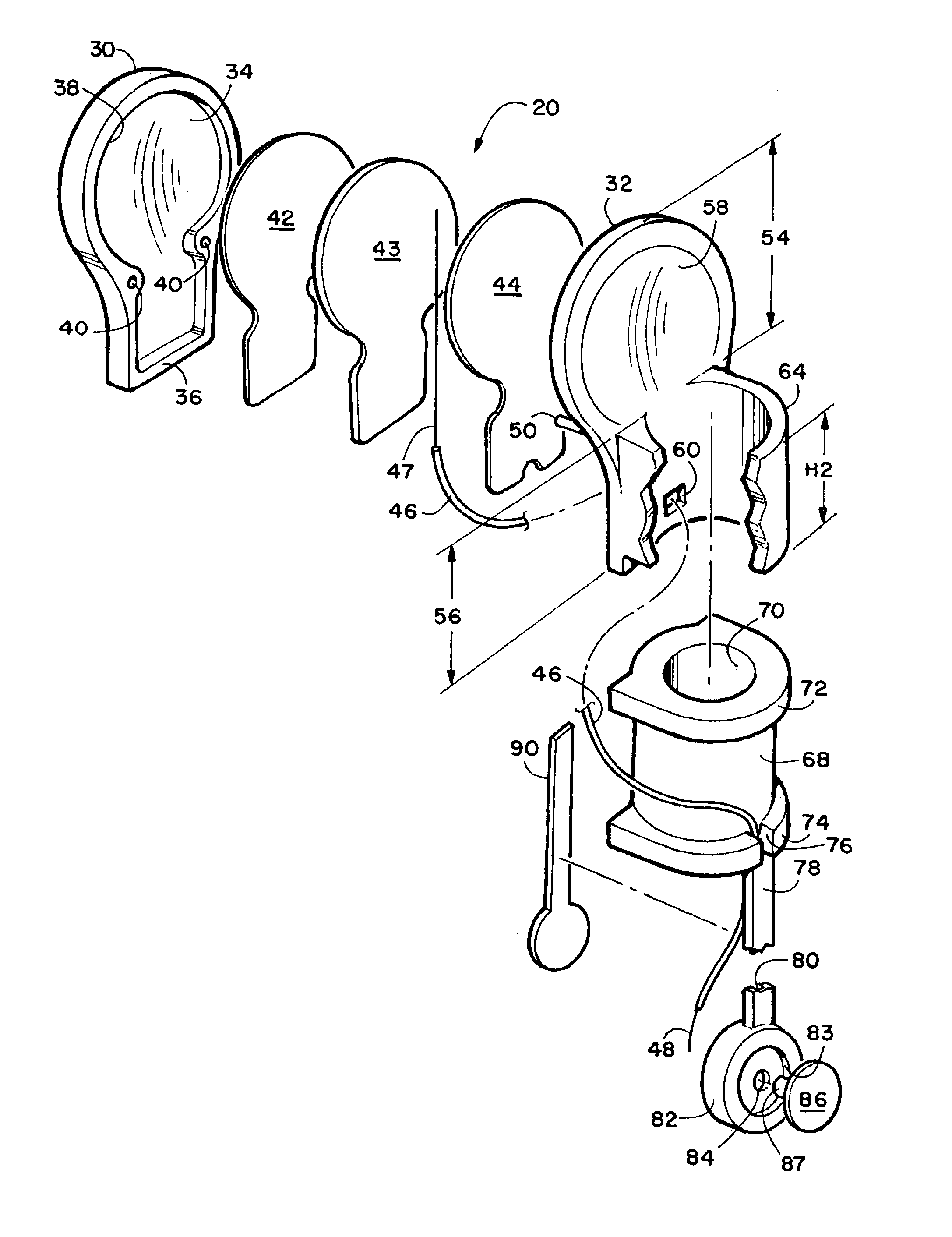
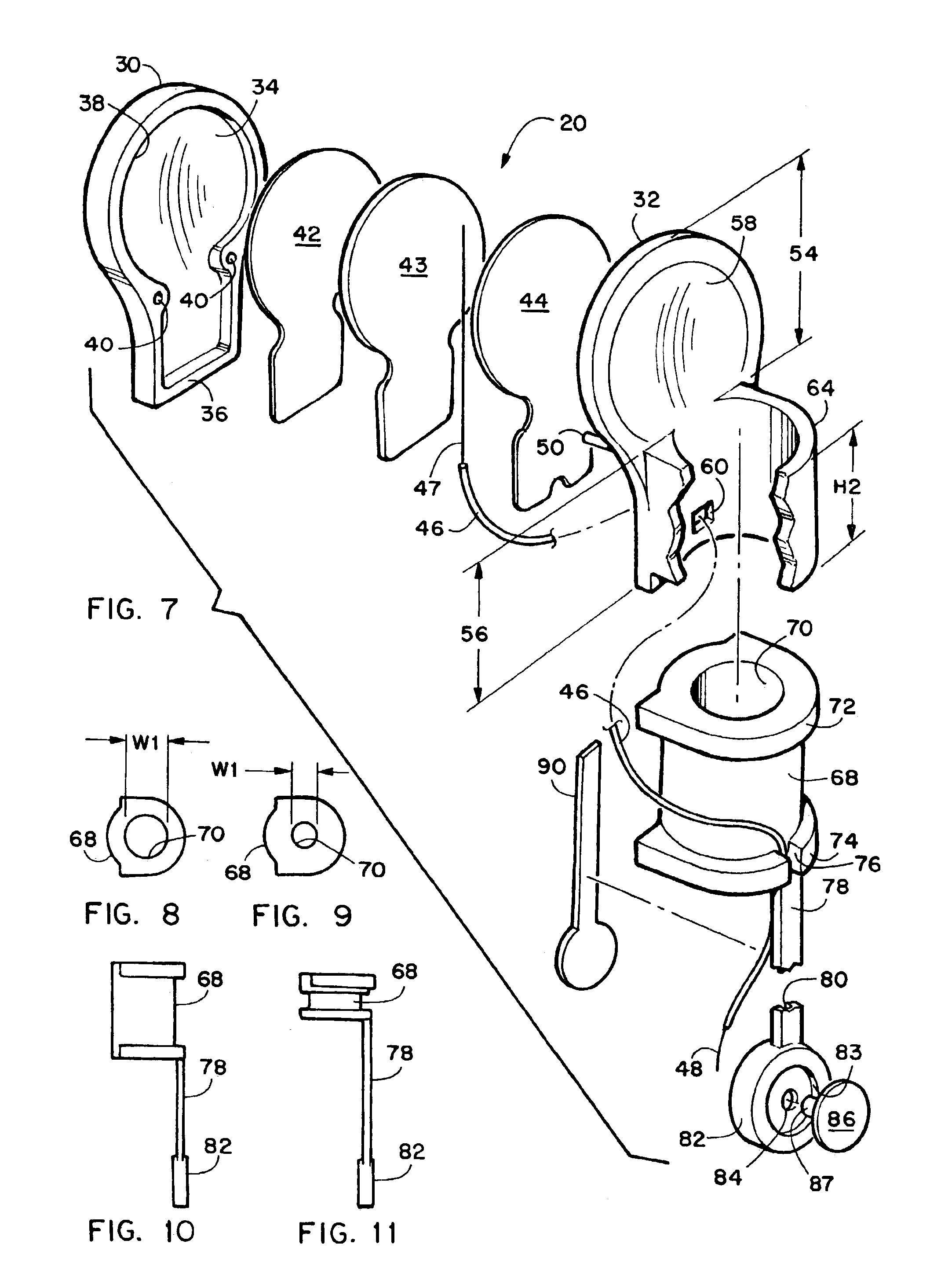
[0013]The rear wall member has a tubular collar formed integrally therewith extending from its rear surface. Removably insertable therein is a tubular rubber boot member having a vertically oriented bore hole. A leg member extends downwardly from the bottom surface of the tubular collar and it has a disk portion formed thereon. A length of electrical conductor wire has insulation removed from its top end that is positioned between and in contact with two of the previously mentioned membranes. The other end of the electrical wire conductor is threaded through an aperture in the lower portion of the rear wall member and threaded around the tubular boot and then down through a groove in the rear surface of the leg member to the disk at its bottom end. The insulation on the bottom end of the wire conductor is removed and placed in contact with the brass rivet button that passes through the disk member. The combined structure of the membrane members and the carbon fiber impregnated plastic material of the RFR shield unit has been successful in blocking the transmission of better than ninety six percent of the radio frequency radiation emanating from the antenna of a wireless phone. This is a remarkable achievement that is superior to anything presently in the market place.

Problems solved by technology

Wireless telephones including, but not limited to cellular telephones, digital telephones, analog telephones, PCS telephones, and personal communication systems (the new generation of wireless communication products), generate radio frequency radiation, including an electromagnetic field (“EMF”), which may prove harmful to persons exposed to such radiation.
There is also concern that such radiation can have a cumulative effect.
However, none of those approaches has been entirely satisfactory.

Method used


Image

  • Radio frequency radiation shield unit for wireless telephones
  • Radio frequency radiation shield unit for wireless telephones
  • Radio frequency radiation shield unit for wireless telephones

Examples


Embodiment Construction

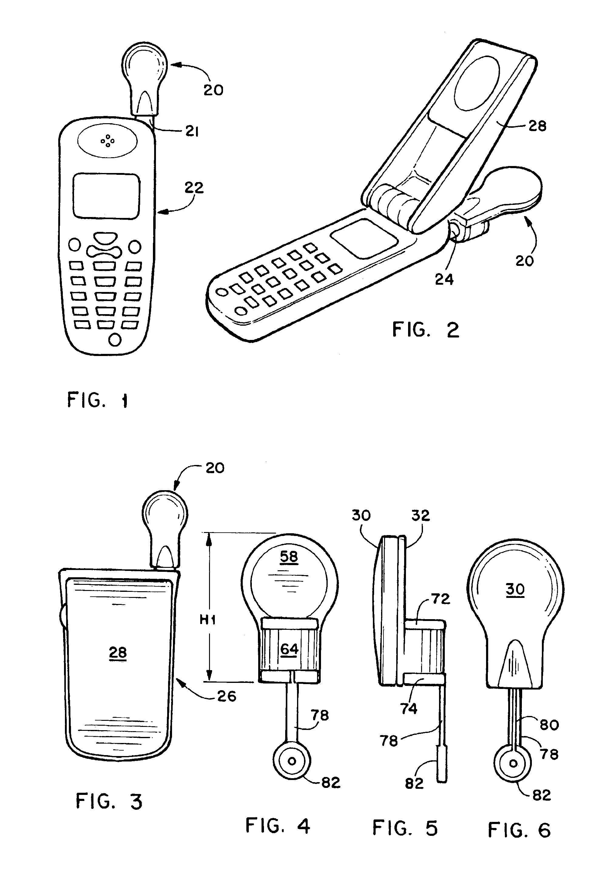
[0025]The novel radio frequency radiation shield unit for wireless telephones will now be described by referring to FIGS. 1-11 of the drawings. The novel radio frequency radiation shield unit is generally designated numeral 20 and in FIG. 1 it is shown installed on the antenna 21 of a non-collapsible telephone 22. In FIG. 2, the novel radio frequency radiation shield unit 20 is shown installed on the antenna 24 of a collapsible cellphone 26. Cellphone 26 has a cover 28 pivotally attached thereto which is shown in the open position in FIG. 3 and this is the position when the cell phone is being used.

[0026]The structure of the radio frequency radiation shield unit 20 is best understood by referring to FIGS. 4-7 of the drawings. It has a front wall member 30 and a rear wall member 32. Front wall member 30 has a concave rear surface 34 and a rearwardly extending flange 36 around its entire perimeter that forms an interior chamber 38. A pair of apertures 40 are formed in the rear surface...


PUM


Abstract

A radio frequency radiation shield unit that is removably mounted on the antenna of a wireless telephone. It has an upright oriented front wall member that is detachably connected to an upright oriented rear wall member. These wall members are fabricated of a plastic material having carbon fibers therein for absorbing and dispersing radiation. A chamber is formed between the front wall member and rear wall member and one or more membranes are positioned therein and these membranes are made of carbon fiber material that has been cut into strips and tightly woven together. A tubular collar is formed on the rear surface of the lower portion of the rear wall member.

Description

BACKGROUND OF THE INVENTION[0001]The present invention is generally related to wireless telephones, and more specifically to a radio frequency radiation shield unit to be installed over the antenna of wireless telephones.[0002]Wireless telephones including, but not limited to cellular telephones, digital telephones, analog telephones, PCS telephones, and personal communication systems (the new generation of wireless communication products), generate radio frequency radiation, including an electromagnetic field (“EMF”), which may prove harmful to persons exposed to such radiation. In recent years, as the number of wireless telephones has grown, so has the concern about tumors or other damage to the brain. Although the level of radiation emitted by such devices is relatively low, the antenna which emits the radiation is close to the head. There is also concern that such radiation can have a cumulative effect.[0003]In the past, there have been some attempts to protect users' of cellula...

Claims


Application Information

Patent Timeline
IPC IPC(8): H01Q1/00H01Q1/52H01Q1/24
CPCH01Q1/52H01Q1/245
Inventor KUNZ, KIM R.
Owner KUNZ KIM R
Learn More