
Adaptive linearizer for RF power amplifiers

a technology of rf power amplifiers and linearizers, applied in amplifiers, amplifier types, amplifier modifications to reduce noise influence, etc., can solve problems such as error signals, error signals, and error signals

Inactive Publication Date: 2005-05-24
COMMSCOPE TECH LLC
View PDF28 Cites 4 Cited by
  • Summary
  • Abstract
  • Description
  • Claims
  • Application Information

AI Technical Summary

Benefits of technology

[0033]According to another aspect of the present invention, an amplifier is provided. The amplifier includes a main amplifier, a main signal adjuster, a first subtracter, and a main controller. The main amplifier generates an intermediate amplified signal. The main signal adjuster couples an input signal to the main amplifier, including at least one complex gain adjuster that is controlled by main control inputs. The first subtracter subtracts a delayed version of the input signal from the intermediate signal, resulting in an error signal. In addition, based on the error signal, a main controller generates main control signals which are provided to the main control inputs of the main signal adjuster. The main controller includes at least one control linearizer which adjusts the main control signals to compensate for nonlinearities in the main signal adjuster's response to the main control inputs.
[0034]According to yet another aspect of the present invention, an amplifier is provided. The amplifier includes a main amplifier, a main signal adjuster, a first subtracter, and a main controller. It also includes an auxiliary amplifier, an auxiliary signal adjuster, a second subtracter, and an auxiliary controller. The main amplifier generates an intermedia

Problems solved by technology

The first subtracter subtracts a delayed version of the input signal from the intermediate signal, resulting in an error signal.
A delayed version of the input signal is subtracted from the intermediate signal, resulting in an error signal.
In addition, an adjusted version of the error signal is amplified, resulting in an amplified version of the error signal.

Method used


Image

  • Adaptive linearizer for RF power amplifiers
  • Adaptive linearizer for RF power amplifiers
  • Adaptive linearizer for RF power amplifiers

Examples


Embodiment Construction

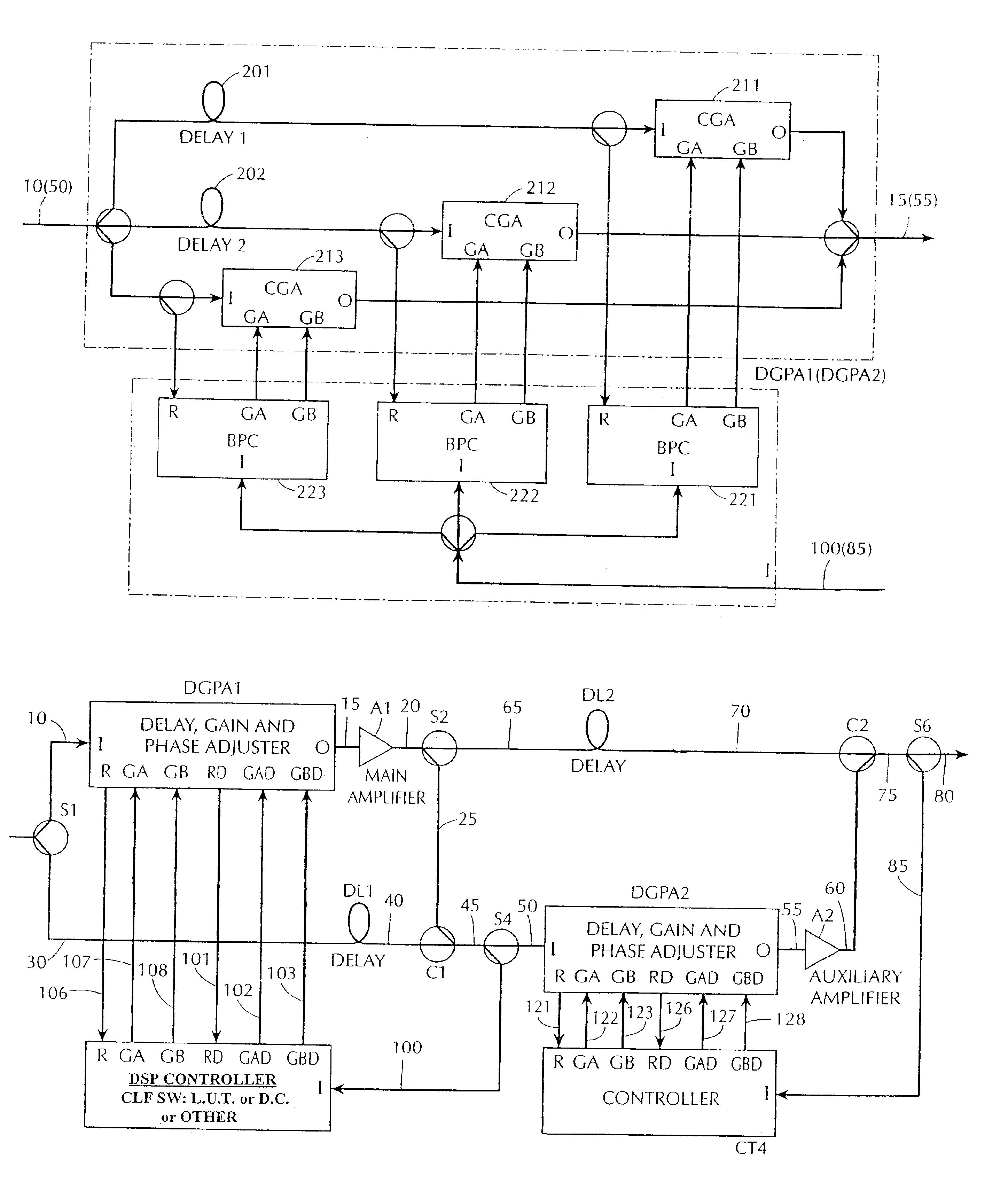
[0049]FIG. 12 shows an improved arrangement for the delay, gain and phase adjuster (DGPA) and the controller CT3 (CT4). This improved DGPA and controller set is used to replace the corresponding components in prior art feedforward amplifiers such as the feedforward amplifier of FIG. 4. Unlike the prior art amplifiers, which have two parallel adjustable branches in the DGPA, the feedforward amplifier in accordance with the present invention includes a larger number of branches.

[0050]In FIG. 12, the input signal 10 is split into three branches. The first branch includes a delay element 201 and a complex gain adjuster (CGA) 211. The second branch includes a delay element 202 and a CGA 212. The third branch includes a CGA 213, but does not include a delay element (although it will have an associated incidental delay inherent in the circuit components and interconnections, which can be ignored). Each of the CGAs 211-213 is independently controlled by a pair of signals GA and GB. These si...


PUM


Abstract

A feedforward amplifier is disclosed in which either the main amplifier or the auxiliary amplifier includes at least three parallel signal paths. Each of the signal paths includes a complex gain adjuster. In addition, a feedforward amplifier is disclosed in which a plurality of control linearizers compensate for nonlinearities in the response of signal adjusters to control inputs.

Description

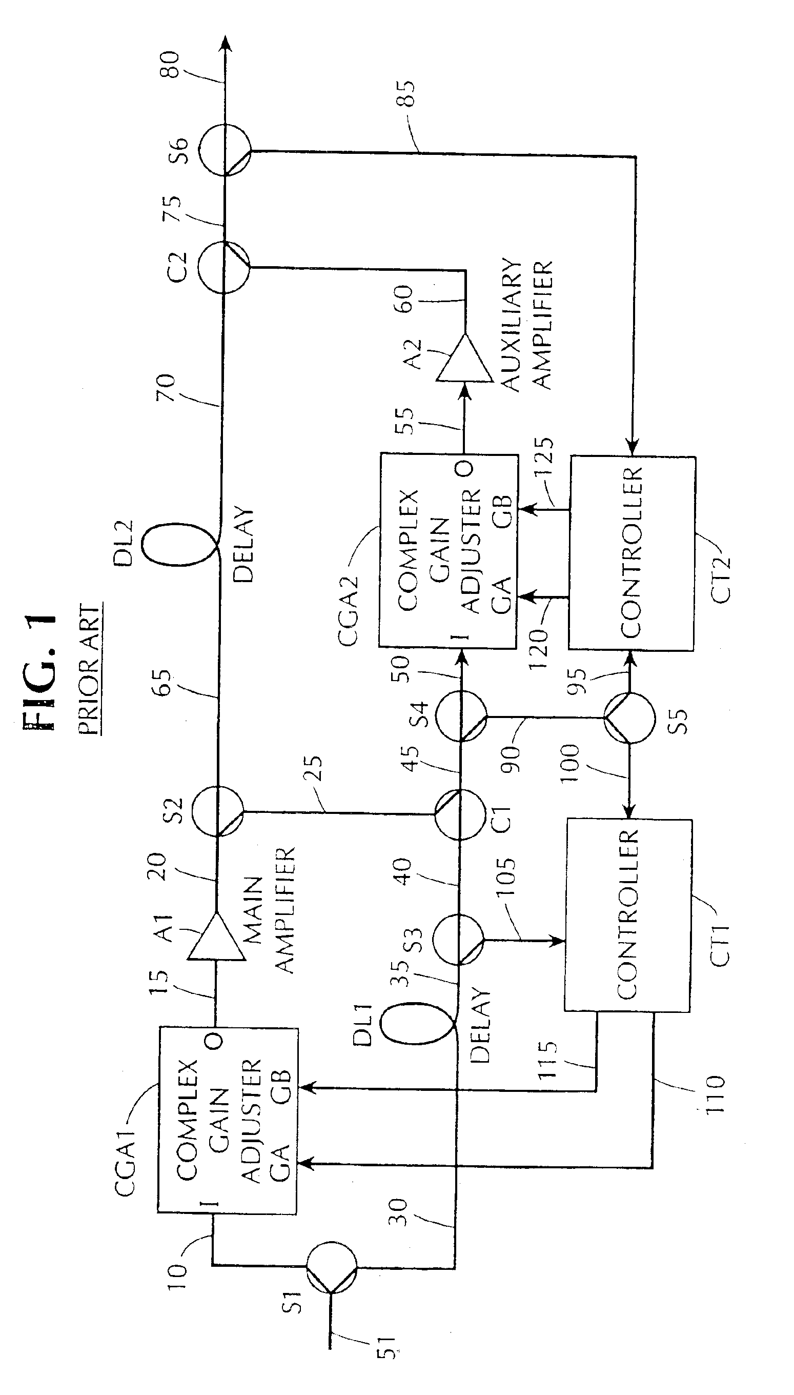
CROSS-REFERENCE TO RELATED APPLICATIONS[0001]This application is a divisional of Application Ser. No. 10 / 122,347 filed Apr. 16, 2002, now U.S. Pat. No. 6,734,732, which is a division of Application Ser. No. 09 / 758,349, filed Jan. 12, 2001, now U.S. Pat. No. 6,414,546 which is a division of Application Ser. No. 09 / 305,312, filed May 5, 1999, now U.S. Pat. No. 6,208,207.BACKGROUND OF THE INVENTION[0002]This application pertains to improvements in linearization of radio frequency (RF) amplifiers to reduce the effects of intermodulation (IM) distortion.[0003]All amplifiers are non-linear to some degree. If the signal carried by the amplifier has an envelope that fluctuates in magnitude, such as a multicarrier signal or a linear data modulation, then the non-linear operation generates intermodulation (IM) products in the amplifier output. These IM products represent unwanted interference in the operating band of the amplifier. Although it is possible to reduce the power of the IM product...

Claims


Application Information

Patent Timeline
IPC IPC(8): H03F1/32H03F3/189
CPCH03F1/3229H03F2200/451
Inventor CAVERS, JAMES K.
Owner COMMSCOPE TECH LLC
Learn More