Electrically controlled very high value floating CMOS resistor

a very high value, cmos resistor technology, applied in the direction of one-port active network, basic electric elements, electric apparatus, etc., can solve the problems of limited poly silicon, large silicon region associated with widespread end resistance value, and physical constraints of integrated circuits that do not allow the inclusion of standard fixed resistors

Inactive Publication Date: 2005-05-24
SARAWI SAID
View PDF2 Cites 10 Cited by
  • Summary
  • Abstract
  • Description
  • Claims
  • Application Information

AI Technical Summary

Benefits of technology

[0009]The circuit arrangement thus effectively converts the at least one grounded resistor coupled to the transistors to a floating resistance device wherein both terminals of the resistance device are available for use in an integrated circuit.

Problems solved by technology

The physical constraints of integrated circuits do not allow for the inclusion of standard fixed resistors as used in non-integrated electrical circuits.
Whilst this technique is feasible, poly silicon is limited in the range of electrical resistance it can present to the order of 1 to 3 kΩ's whilst at the same time consuming a relatively large region of silicon associated with widespread end resistance value.
As the ability to provide capacitive devices in integrated circuits is limited, there is a requirement for larger values of electrical resistance to satisfy the time constant requirements.

Method used


Image

  • Electrically controlled very high value floating CMOS resistor
  • Electrically controlled very high value floating CMOS resistor
  • Electrically controlled very high value floating CMOS resistor

Examples


Embodiment Construction

[0031]The following detailed description of the invention refers to the accompanying drawings. Although the description includes exemplary embodiments, other embodiments are possible, and changes may be made to the embodiments described without departing from the spirit and scope of the invention.

[0032]It has been recognised that resistors and transconductors have an important role in a wide variety of applications such as signal processing and neural networks, which generally utilise analogue VLSI circuits.

[0033]In the following description it is assumed that the source and the back gate for the corresponding n and p type MOS transistor are connected together, unless it is specifically indicated otherwise.

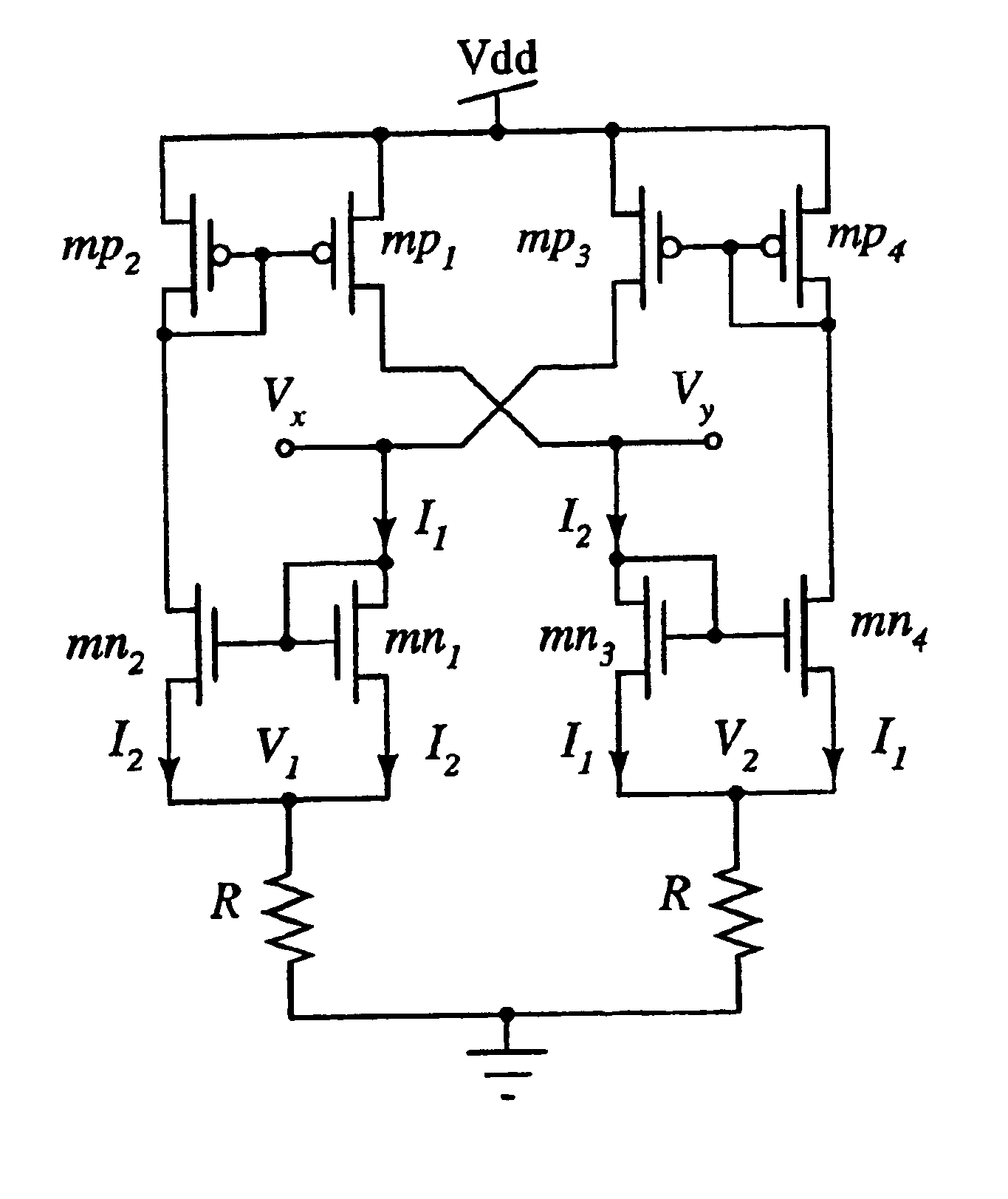
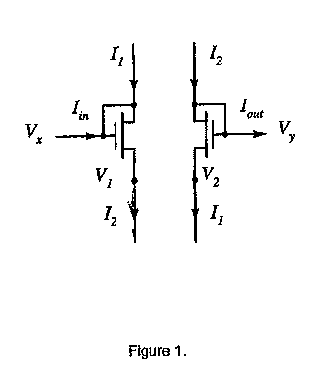
[0034]The circuit arrangement of a preferred embodiment of the invention includes two diode connect matched transistors operating in the saturation region.

[0035]With reference to FIG. 1, the circuit arrangement details two diode connected matched transistors operating in their sat...


PUM


Abstract

The present invention provides a circuit arrangement to convert fixed, or grounded resistors, to floating resistors. In particular, the circuit arrangement provides for the coupling of active electrical resistance devices to provide a relatively high value electrical resistance between two non-grounded nodes of the circuit arrangement in the order of Giga-ohms. The invention further provides for the magnitude of the floating electrical resistance to be determined by the magnitude of electrical current supply thus providing a means to select the magnitude of the floating electrical resistance by selecting by selecting the magnitude of electrical current supply. The circuit arrangement requires relatively few active devices and consumes a relatively small amount of electrical power in operation. The floating resistor of the present invention may be used in applications where a relatively high value resistor consuming a relatively small area of silicon, exhibiting relatively good linearity and wide dynamic range are required. Applications for such a device include neural networks, image processing and vision systems.

Description

FIELD OF THE INVENTION[0001]This invention relates generally to a means of providing a high value floating resistor for integrated electrical circuits and a method of producing such a high value floating resistor. More particularly, the invention relates to a circuit arrangement that provides for coupling to a grounded resistance device such that the circuit arrangement presents a high value resistance between two floating, or non-grounded, nodes of the circuit arrangement.BACKGROUND TO THE INVENTION[0002]The physical constraints of integrated circuits do not allow for the inclusion of standard fixed resistors as used in non-integrated electrical circuits. However, in various applications, the use of resistors, or resistance devices, in an integrated circuit is beneficial.[0003]As a result, various techniques have been employed in order to provide an electrical resistance device in an integrated circuit that may be manufactured during the process of manufacturing the integrated circ...

Claims


Application Information

Patent Timeline
Patent Type & Authority Patents(United States)
IPC IPC(8): H03H11/46H03H11/00
CPCH03H11/46H03H11/53
Inventor AL-SARAWI, SAID
Owner SARAWI SAID
Why Eureka
Try Eureka