
Portable scanning electron microscope

a scanning electron microscope and portable technology, applied in the field of portable scanning electron microscopes, can solve the problems of limited resolution, address the mobility of the electron microscope system, and develop the first electron microscope, so as to reduce the amount of vacuum pumping needed, reduce the size of the portable power source, and reduce the size of the optical system

Inactive Publication Date: 2005-05-24
GROSS HARALD
View PDF7 Cites 20 Cited by
  • Summary
  • Abstract
  • Description
  • Claims
  • Application Information

AI Technical Summary

Benefits of technology

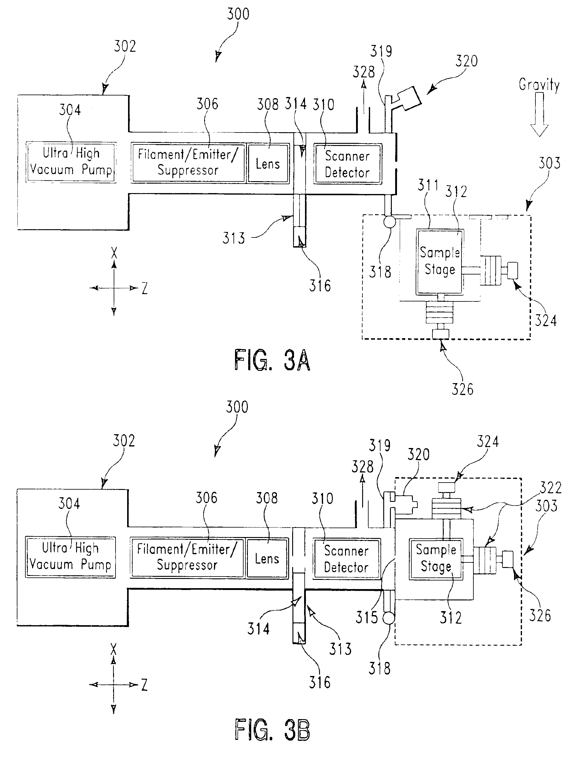
[0008]We have developed a particular combination of elements and devices which enables the portability of a scanning electron microscope (SEM). In particular the combination enables a small size, typically less than about 50 liters, a manageable weight, typically less than about 15 kg, and a low power requirement, typically less than about 100 W, which permits operation using power supplied from a battery source. Higher performance versions way exhibit increased weight, which is typically less than about 45 kg, and these may be portable with the assistance of a dolly (rolling cart) or with the assistance of attached wheels and pulling appendage.
[0009]The portable SEM makes use of low beam energies, in the range of about 1 keV to 10 keV, more typically in the range of about 1 keV to 5 keV, and even more typically within a range of about 1 keV to 3 keV, since this latter range is more advantageous because of smaller size and weight requirements. These low beam energies allow analytical imaging of, for example, dielectrics without charging effects. The low beam energies also reduce damage to biological samples analyzed using the portable scanning electron microscope. The typical magnification of the portable SEM enables imaging of feature sizes as small as about 50 nm for a back pack-sized SEM and about 10 nm for a dolly SEM. This makes the portable SEM useful for analysis of metallurgical grain boundaries.
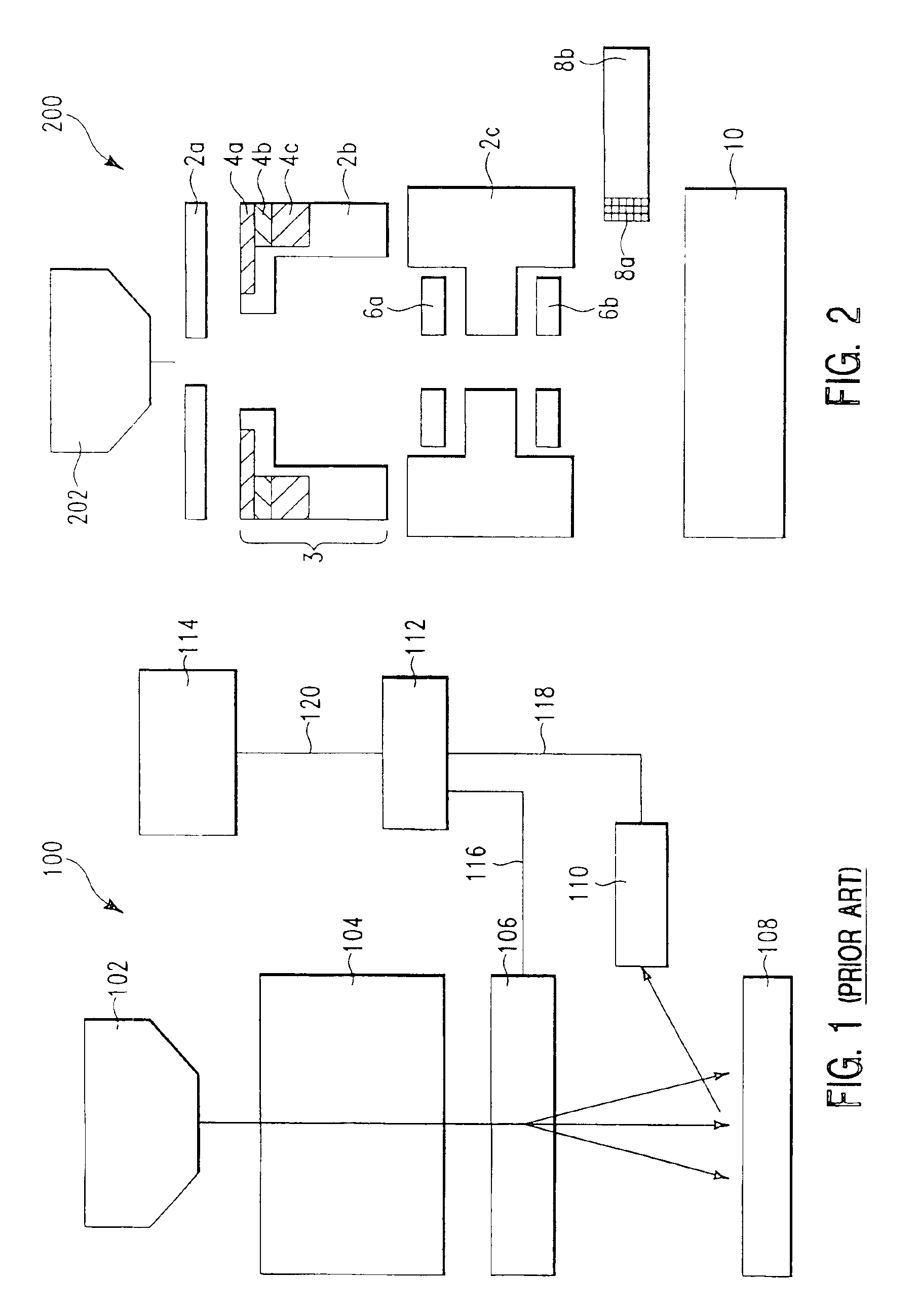
[0012]The main attributes of the design which enable the portable SEM are: use of a minimum number of focusing elements to reduce the necessary electronics; avoidance of current drawing elements (all elements are permanent magnetic and / or electrostatic) to reduce the size of a portable power source, for example batteries; an electron optical system which is made small, by way of example using micromachined (for example, MEMS) elements, so that the entire optical system exhibits a footprint which is less than about 4 square centimeter, typically less than about 1 square centimeter, and exhibits a length which is less than about 15 centimeters, typically less than about 10 cm. Reduction in the optical system volume reduces the amount of vacuum pumping necessary, thereby reducing both power consumption and vacuum pump size and weight.

Problems solved by technology

The first electron microscopes were developed in the early 1930's and were limited in their resolution by problems such as specimen heating and specimen damage due to high electron energy exposure in general.
The description in the Khursheed et al. patent illustrates a compact electron optics, but does not address the mobility of the electron microscope system which is significantly affected by elements other than the electron optics.
Again, this reference focuses on miniaturized electron optics but does not describe an entire system which is sufficiently mobile to be independently used at locations which are difficult to access.
However, the overall system requirements, such as power supply and pump down requirements for this system were considerably different from the requirements for most applications useful on earth.
In addition the sample stage described was inadequate for use in a portable scanning electron microscope.

Method used


Image

  • Portable scanning electron microscope
  • Portable scanning electron microscope
  • Portable scanning electron microscope

Examples


Embodiment Construction

[0029]As a preface to the detailed description, it should be noted that, as used in this specification and the appended claims, the singular forms “a”, “an”, and “the” include plural referents, unless the context clearly dictates otherwise.

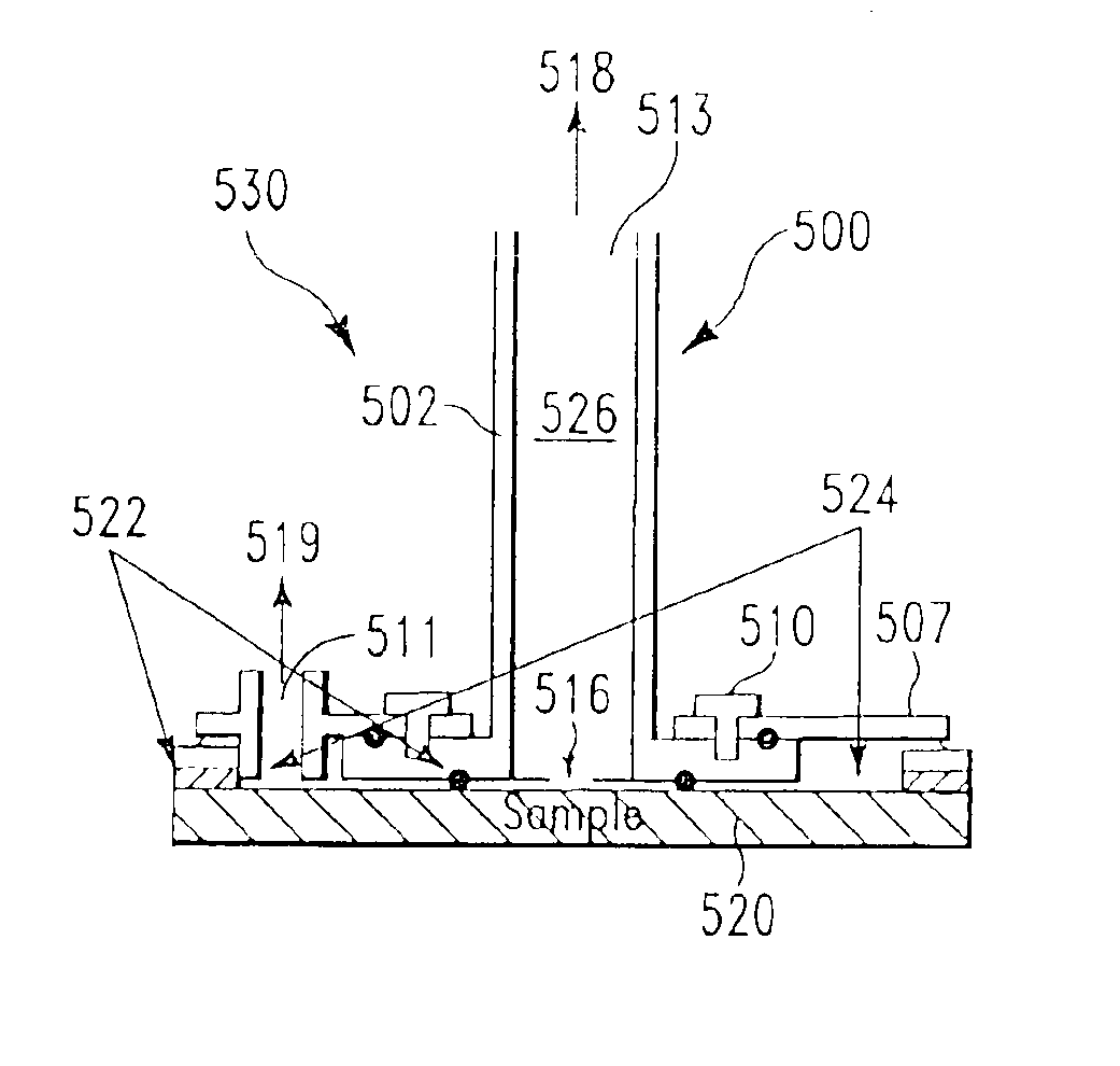
[0030]As mentioned in the Background Art section above, the present invention pertains to a portable SEM which may either be of a size and weight that it can be carried in a back pack or which may be of a size and weight that can be moved about on a dolly. The dolly-portable SEM may be used for inspection at manufacturing sites where space is constrained or may be loaded into the back of an off road vehicle or pickup truck and taken where needed, provided the landscape topography can be traversed by the dolly. In particular the combination of elements, devices and modules which make up the portable backpack SEM enable a small size, typically less than about 50 liters, a manageable weight, typically less than about 15 kg, and a low power requiremen...


PUM


Abstract

We have developed a particular combination of elements and devices which enables the portability of a scanning electron microscope (SEM). In particular the combination enables a small size, typically less than about 50 liters, a manageable weight, typically less than about 15 kg, and a low power requirement, typically less than about 100 W, which permits operation using power supplied from a portable source such as a battery. Higher performance versions may exhibit increased volume in the range of about 150 liters, increased weight, in the range of 45 kg, and a power requirement in the range of 300 W. The higher performance version of the portable scanning electron microscope may be portable with the assistance of a dolly (rolling cart) or with the assistance of attached wheels and pulling appendage.

Description

FIELD OF THE INVENTION[0001]In general, the present invention relates to a portable scanning electron microscope which is sufficiently small in size and light weight that it can be transported to and used at locations which have not been possible with present day scanning electron microscopes. Further, the invention enables the inspection of samples which will not fit into a standard vacuum chamber.BRIEF DESCRIPTION OF THE BACKGROUND ART[0002]The electron microscope was developed to enable imaging of objects and substrates which are too small to be imaged by light microscopes, due to the length of the light wave. The first electron microscopes were developed in the early 1930's and were limited in their resolution by problems such as specimen heating and specimen damage due to high electron energy exposure in general. Considerable work was needed to produce a proper condenser, polepieces for objective and projective, as well as airlocks for specimens and photoplates.[0003]Today, the...

Claims


Application Information

Patent Timeline
IPC IPC(8): H01J37/28G01Q30/02G01Q30/16G01Q30/18
CPCH01J37/28H01J2237/3175H01J2237/18H01J2237/16
Inventor GROSS, HARALD
Owner GROSS HARALD
Learn More