Brushless scrub head for surface maintenance

a scrub head and surface technology, applied in the direction of floor scrubbers, cleaning equipments, cleaning using liquids, etc., can solve the problems of inadequate brush-type scrubber systems, and achieve the effect of high efficiency

Inactive Publication Date: 2005-05-24
TENNANT COMPANY
View PDF52 Cites 47 Cited by
  • Summary
  • Abstract
  • Description
  • Claims
  • Application Information

AI Technical Summary

Benefits of technology

[0010]Further, in accordance with the present invention, the brushless scrub head is constructed to include a highly efficient solution recovery system.

Problems solved by technology

However, in some high demand or difficult surface maintenance applications and environments, brush-type-scrubbing systems may be inadequate.

Method used


Image

  • Brushless scrub head for surface maintenance
  • Brushless scrub head for surface maintenance
  • Brushless scrub head for surface maintenance

Examples


Embodiment Construction

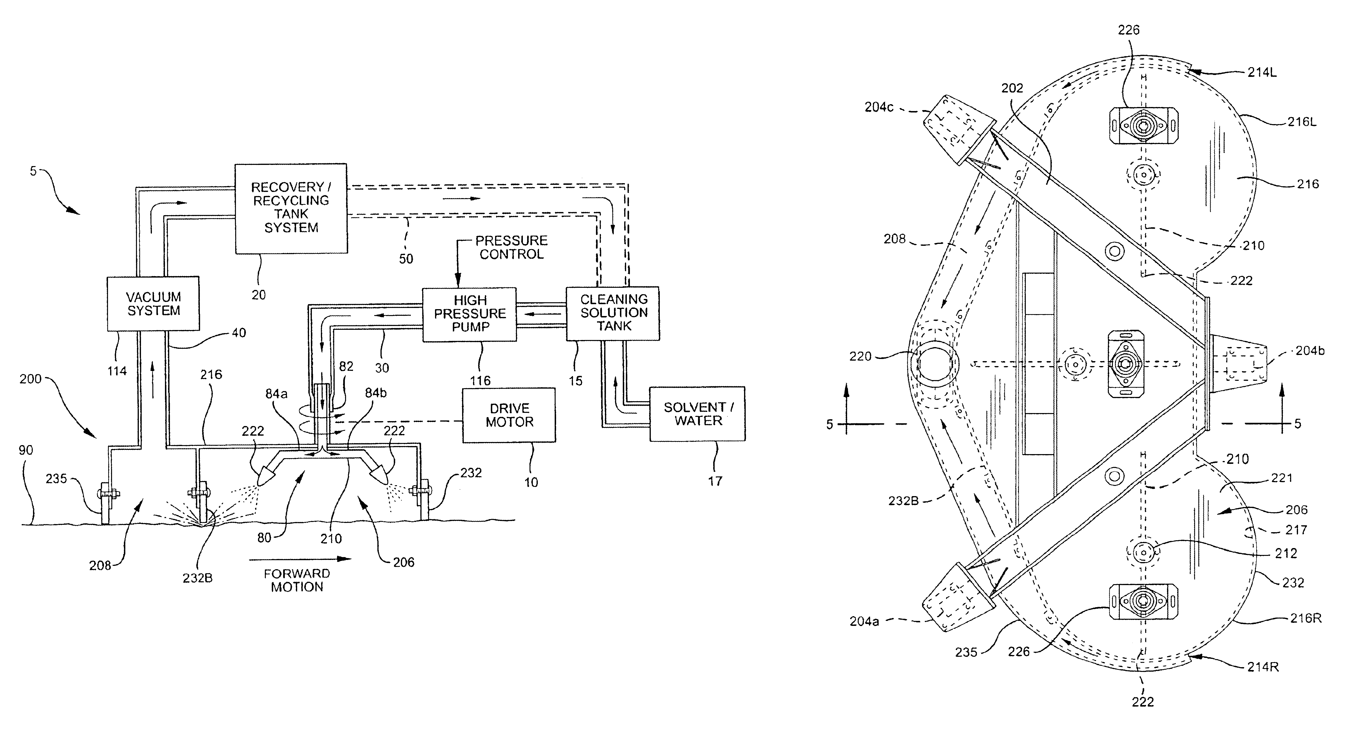
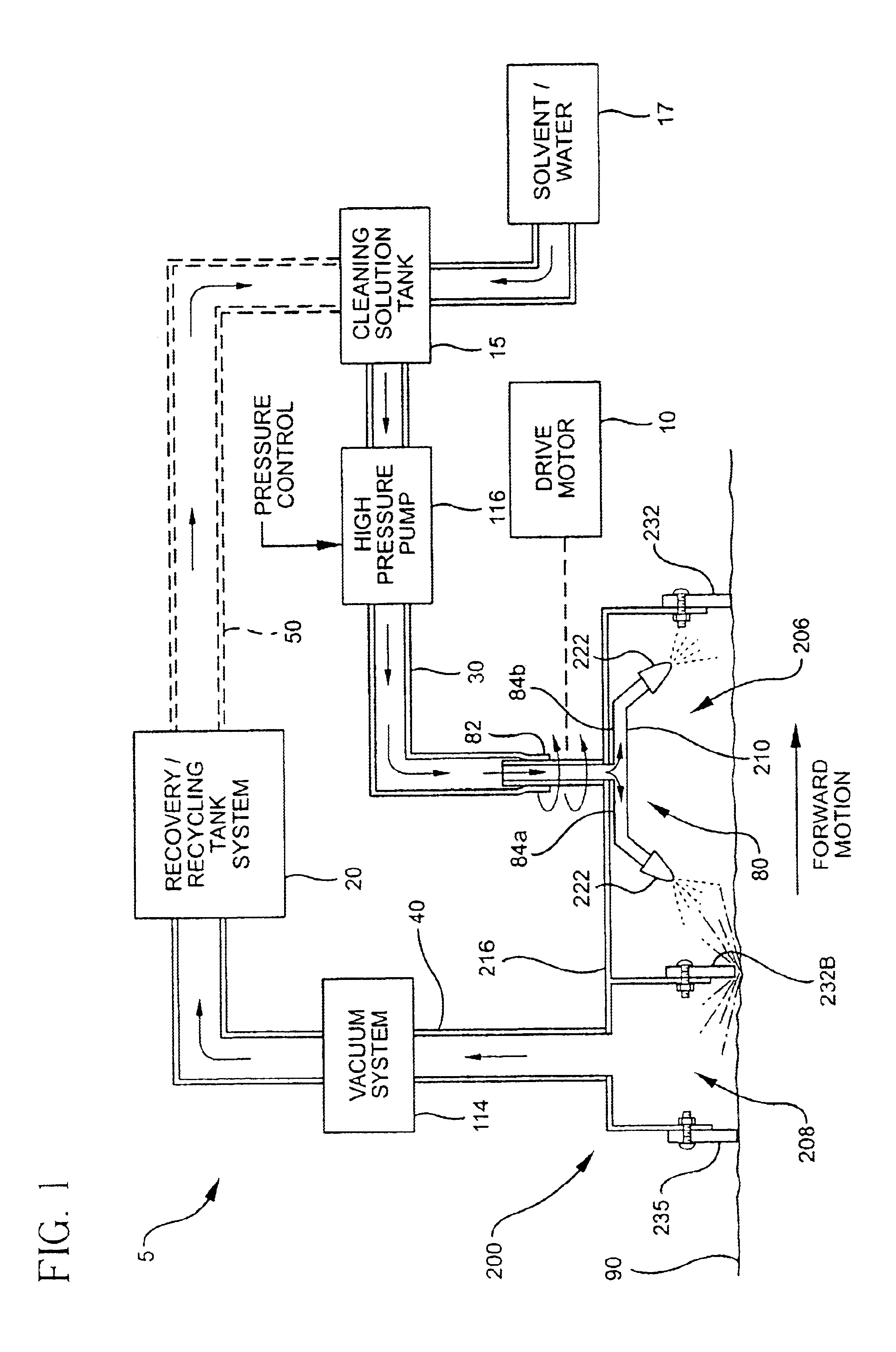
[0019]Illustrated in FIG. 1 is a block diagram of a scrubless head cleaning system 5 in accordance with the present invention and further employing a scrubless cleaning head 200 embodying further several aspects of the present invention. More specifically, a rotatable solution spraying wand system 80 includes a fluid carrying shaft 82 coupled to fluid carrying wands 84a and 84b, each terminating with a nozzle 222. Nozzle 222 and wands 84a and 84b are configured to have a selected spraying pattern for directing a solution at a selected angle relative to a horizontal surface 90. Shaft 82 is coupled to drive motor 10 for causing shaft 82 to spin at a selected spin rate. Drive motor 10 may be a hydraulic motor, an electric motor, an air motor or combinations thereof.

[0020]In one embodiment of the invention, scrubless cleaning head 200 is constructed to form an open ended spraying chamber 206 and an open ended vacuum chamber 208, each chamber 206, 208 being open to the surface to be clea...


PUM


Abstract

A device and method of use for cleaning a ground surface with pressurized cleaning solution is disclosed. The device includes a transportable deck having at least a first chamber and a second chamber, each first and second chamber being in open communication with the surface, said first chamber having a nozzle for directing a pressurized cleaning solution toward the ground surface, and said second chamber having a vacuum outlet for removing cleaning solution and debris from the surface. Additional embodiments of the present invention may include a solution recycling system for reusing recovered solution.

Description

CROSS REFERENCE TO RELATED APPLICATION[0001]This application claims the benefit of priority of U.S. Ser. No. 60 / 295,106, filed May 31, 2001, pursuant to 35 U.S.C. §119, and the entire disclosure of which is incorporated in its entirety by reference herein.FIELD OF THE INVENTION[0002]The present invention relates generally to surface maintenance or conditioning machines, and particularly those machines employing one or more surface maintenance or conditioning appliances or tools that perform one or more tasks including, among others, scrubbing, sweeping, and vacuuming. More specifically, the present invention is particularly directed to a combination high-pressure spray cleaning system and a spent-solution recovery system.BACKGROUND OF THE INVENTION[0003]Brush-type scrubbing systems and appliances are of course well known for surface maintenance, particularly floor surfaces. However, in some high demand or difficult surface maintenance applications and environments, brush-type-scrubb...

Claims


Application Information

Patent Timeline
Patent Type & Authority Patents(United States)
IPC IPC(8): E01H1/00E01H1/10
CPCE01H1/103
Inventor GEYER, ROBERT A.HAMLINE, ANTHONY JOHNTAYLOR, IANPEARCE, CHRISTOPHER K.
Owner TENNANT COMPANY
Why Eureka
Try Eureka