Fluid cannon positive displacement pump

a positive displacement pump and cannon technology, applied in the direction of liquid fuel engines, rotary piston liquid engines, machines/engines, etc., can solve the problems of limited application, relatively complex construction of positive displacement pumps, and vanes that can only handle limited pressure, so as to achieve higher fluid pressure and handle higher pressure

Active Publication Date: 2005-05-24
1564330 ONTARIO
View PDF7 Cites 6 Cited by
  • Summary
  • Abstract
  • Description
  • Claims
  • Application Information

AI Technical Summary

Benefits of technology

[0011]The pump according to the present invention permits greater vane surface area to act on fluids within the chamber, providing higher handling rates for fluid volumes. As well, since the vanes are supported at each end by the rotor disks, a non-binding action of the vanes is achieved along with the ability of the vanes to withstand higher fluid pressures during operation.

Problems solved by technology

As well, the vanes can handle only limited pressure.
Traditionally, positive displacement pumps have been of relatively complex construction and have been limited in their applications.

Method used


Image

  • Fluid cannon positive displacement pump
  • Fluid cannon positive displacement pump
  • Fluid cannon positive displacement pump

Examples


Embodiment Construction

[0021]In the following description, similar features in the drawings have been given similar reference numerals.

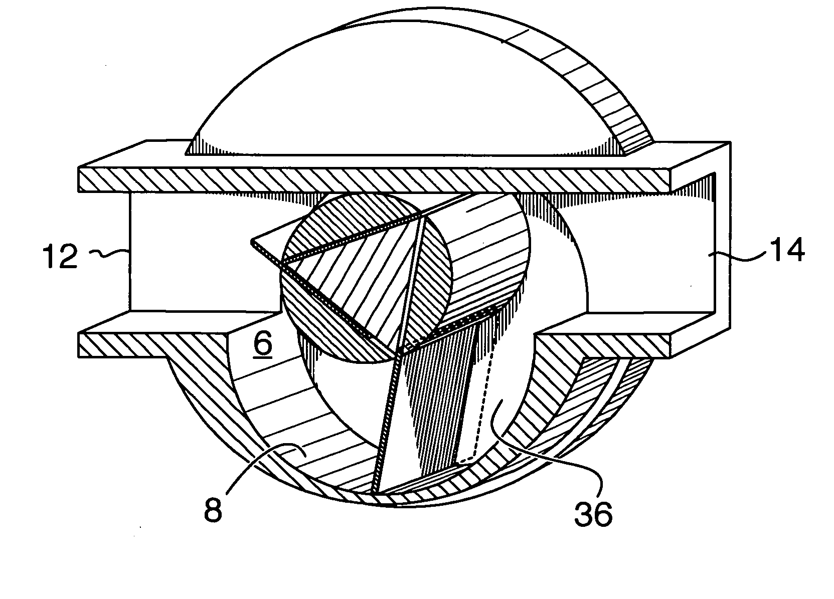
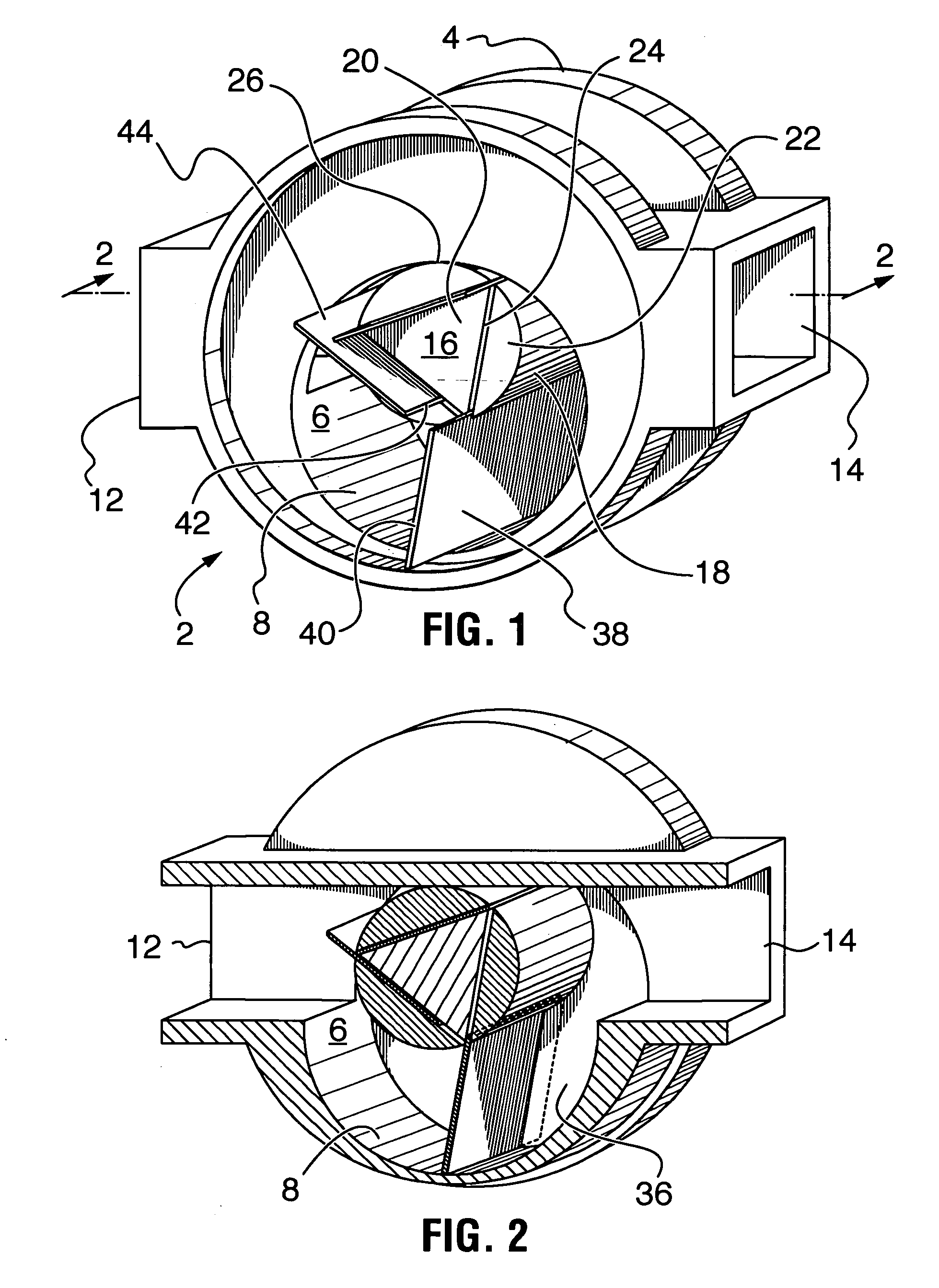
[0022]Turning to FIGS. 1 and 2, there is illustrated a positive displacement pump 2 in accordance with the present invention, having a casing 4 with an interior chamber 6 having a side wall 8 and end walls (one of which has been removed on the near side of FIG. 1). An inlet 12 and an outlet 14 are oppositely spaced on casing 4 as illustrated, and communicate with chamber 8.

[0023]The side wall of chamber 8 may be cylindrical, with a circular bore, as illustrated in FIGS. 1 to 3, or may have an alternative shape such as the generally kidney shape of FIGS. 6 and 7, more details of which will be set out subsequently.

[0024]A rotor 16 is provided with a cylindrical outer surface 18, the rotor being driven by an appropriate drive means (not illustrated). In the illustrated embodiment of FIG. 1 to 3, rotor 16 comprises a triangular core 20 (of equilateral triangular cross section)...


PUM


Abstract

A positive displacement pump comprising a casing having an interior chamber and an inlet and an outlet oppositely spaced within the chamber. A rotor with a cylindrical outer surface is secured in offset position within the chamber. An end disk is secured to each end of the rotor. Three planar vanes are provided, each having sides and inner and outer edges. The sides of the vanes are seated within the end disk slots. The outer edges of the vanes are in constant contact with the side wall of the chamber. The inner edges of the vanes are constantly movably seated in the rotor slots during operation of the pump. The slots in the rotor within which the vanes are seated are formed along a chord when the rotor is viewed in lateral cross section and are orientated so that their planes lie at 60° angles to the planes of adjacent slots.

Description

FIELD OF THE INVENTION[0001]The present invention relates to the novel construction of positive displacement pump for fluids, and more particularly to a rotary piston pump.BACKGROUND OF THE INVENTION[0002]Rotary pistons, in the nature of encased, eccentrically positioned rotors with radially extending vanes which move in and out of the rotors, depending upon their position on the rotational cycle of the rotor, used, for example as pumps or turbines, are known. One such device is described in U.S. Pat. No. 6,554,596 of Albert and David Patterson issued Apr. 29, 2003, in which the vane movement, in and out of the rotor, is achieved by cam surfaces within the casing which act on both inner and outer edges of the vanes.[0003]In my co-pending U.S. patent application Ser. No. 10 / 680,236 entitled “Rotary Pistons”, the outward movement of the vanes is achieved by upward extensions of shoulders at the sides of each vane, which upward extensions contain pins which are seated in races continuo...

Claims


Application Information

Patent Timeline
Patent Type & Authority Patents(United States)
IPC IPC(8): F01C21/00F01C21/08F04C2/00F04C2/344
CPCF01C21/0809F04C2/3442F01C21/0845
Inventor PATTERSON, ALBERT W.
Owner 1564330 ONTARIO
Why Eureka
Try Eureka