H-infinity control and gain scheduling method for electric power assist steering system

a steering system and electric power technology, applied in the direction of steering initiation, instruments, vessel construction, etc., can solve the problems of closed loop control system, component deterioration, and difficulty in maintaining stability and robustness of conventional steering controllers, and achieve stable and robust control system, enhanced stability and robustness of the system, and desired steering feel.

Inactive Publication Date: 2005-05-24
FORD GLOBAL TECH LLC
View PDF27 Cites 9 Cited by
  • Summary
  • Abstract
  • Description
  • Claims
  • Application Information

AI Technical Summary

Benefits of technology

[0010]According to other aspects of the present invention, an electric power assist steering system for a vehicle and a control system for controlling electric motor torque assist to an electric power assist steering system for a vehicle are provided. The electric power assist steering system includes a steering assembly including a steering wheel connected to a steering column, and an electric motor operatively engaged with the steering assembly for supplying steering torque assist. The system also includes a torque detector for detecting driver torque and generating a driver torque signal indicative thereof, and a steering column sensor for sensing steering angle of the steering column and generating a signal indicative thereof. The system further includes a first H-infinity controller coupled in a feedback control loop for generat

Problems solved by technology

Due to inevitable modeling errors, sensor noises, and external disturbances, the steering system controller generally must perform robustly in the presence of such uncertainties.
To control this type of steering system at a very high gain with the boost curve, it is typically difficult for conventional steering controllers to maintain the stability as well as the robustness, i.e., component deterioration, mechanical non-linearities, and road

Method used


Image

  • H-infinity control and gain scheduling method for electric power assist steering system
  • H-infinity control and gain scheduling method for electric power assist steering system
  • H-infinity control and gain scheduling method for electric power assist steering system

Examples


Embodiment Construction

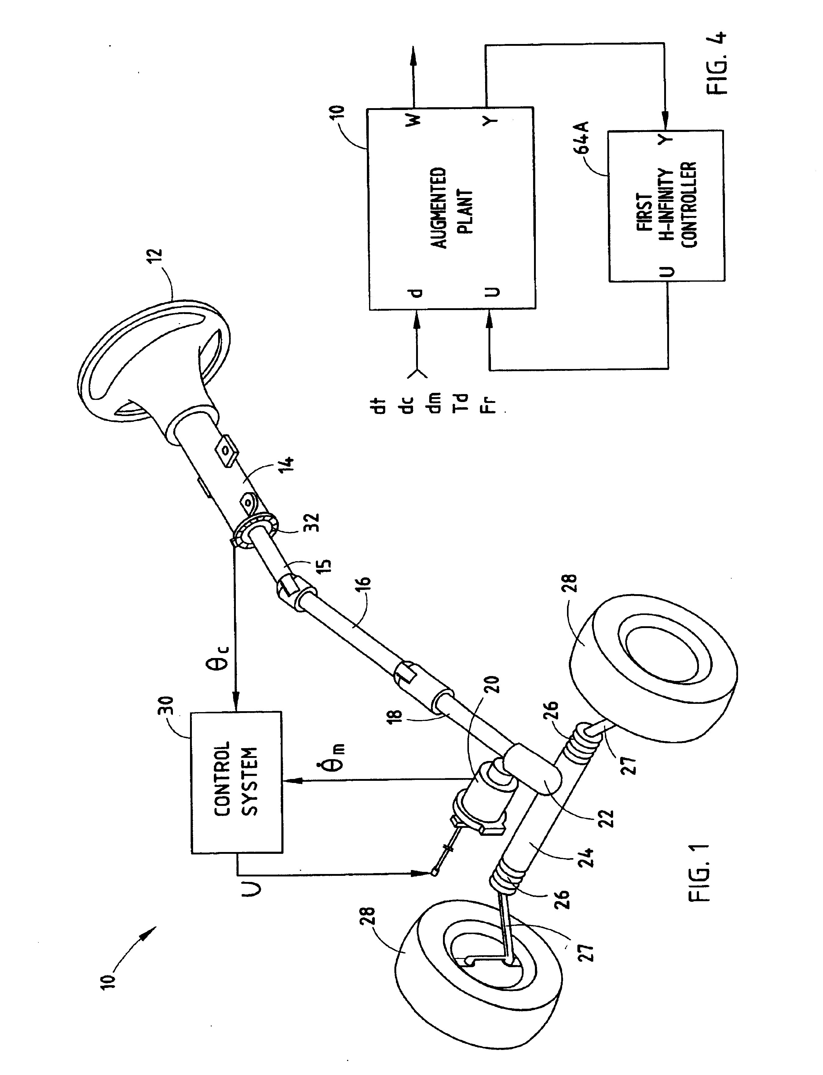
[0019]Referring to FIG. 1, an electric power assist steering (EPAS) system 10 equipped with a control system 30 according to the present invention is illustrated for use in steering a wheeled vehicle, such as a motor vehicle. The steering system 10 is described herein in connection with the power assisted steering of a pair of road wheels 28, such as the front wheels of the motor vehicle, adapted to be engaged in friction contact with the ground, such as a roadway. However, it should be appreciated that the steering system 10 of the present invention may be employed to steer any number of front and / or rear wheels of a steered vehicle.

[0020]The electric power assist steering system 10 has a steering assembly which includes a rotatable steering wheel 12 that is generally disposed in the passenger compartment of the vehicle and is manually rotatable by the driver of the vehicle to steer the road wheels 28. The steering assembly also includes a steering column 14 operatively coupled to ...


PUM


Abstract

A steering system (10) and method (70) for controlling the steering of a vehicle having a steering assembly including a steering wheel (12), a steering column (14) connected to said steering wheel (12), and an electric motor (20) operatively engaged with the steering assembly for supplying torque assist. A steering angle sensor (32) is employed for sensing an angular position θc of the steering column (14). The steering system has first and second H-infinity controllers (64A and 64B) coupled in a feedback path (44) for generating first and second feedback signals as a function of the driver torque and first and second characteristics (JC and KC) of the steering system. One of the first and second feedback signals is selected and the selected feedback signal is combined with a feedforward signal to generate a motor control signal (U) as a function of the estimated torque.

Description

CROSS-REFERENCE TO RELATED APPLICATION[0001]This application is a divisional of application Ser. No. 10 / 012,060, entitled “H-INFINITY CONTROL AND GAIN SCHEDULING METHOD FOR ELECTRIC POWER ASSIST STEERING SYSTEM,” filed on Oct. 20, 2001, now issued as U.S. Pat. No. 6,651,771, which is hereby incorporated herein by reference.FIELD OF THE INVENTION[0002]The present invention generally relates to vehicle steering systems, and more particularly relates to an electric power assist steering system and method of controlling electric power steering assist for a steered vehicle.BACKGROUND OF THE INVENTION[0003]Conventional steering of a wheeled motor vehicle is typically achieved by the vehicle operator (driver) rotating a steering wheel that is arranged in the passenger compartment of the vehicle to turn the steerable road wheels. Conventional steering systems generally include a rack and pinion type steering assembly operatively coupled to the road wheels and a steering column coupled betwe...

Claims


Application Information

Patent Timeline
IPC IPC(8): B62D6/10B62D6/08B62D5/04
CPCB62D6/10B62D5/0463
Inventor CHABAAN, RAKAN C.
Owner FORD GLOBAL TECH LLC
Why Eureka
Try Eureka