
Water heater with a flame arrester

Inactive Publication Date: 2005-05-24
PALOMA
View PDF4 Cites 10 Cited by
  • Summary
  • Abstract
  • Description
  • Claims
  • Application Information

AI Technical Summary

Benefits of technology

[0008]Hence, an object of the invention is to solve the problem described above and to provide a water heater with a flame arrester capable of preventing trouble occurring with the shortage of the air supply due to the clogging of the flame arrester.
[0009]Moreover, another object of the invention is to provide a water heater with the shortage of the air supply due the clogging of the flame arrester as well as capable of saving the works of cleaning of the flame arrester for forcing the clogging itself of a flame arrester due to dust, the combustion products and the like not to be easily generated.
[0015]The objects are further accomplished by the flame arrester arranged beneath the foregoing burner horizontally, and further providing falling prevention means for preventing combustion products from falling from the upper side to the flame arrester.

Problems solved by technology

However, since the opening of the flame arrester 6 is small as described above, it becomes easily clogged by combustion products such as dust, a drain generated by the combustion of the gas or the like.
Therefore, if the flame arrester 6 had been clogged by dust or combustion products, an incomplete combustion state would be occurred due to the shortage of air supply within the combustion chamber 3, the state where carbon monoxide gas increases could be generated within the room around the water heater, and people within the room might have been suffered from carbon monoxide poisoning or the like.
Moreover, for the purpose of preventing sufferings from such carbon monoxide poisoning or the like, it is necessary to frequently do the work for cleaning the clogging of the flame arrester, and it has been very much troublesome.

Method used


Image

  • Water heater with a flame arrester
  • Water heater with a flame arrester
  • Water heater with a flame arrester

Examples


first embodiment

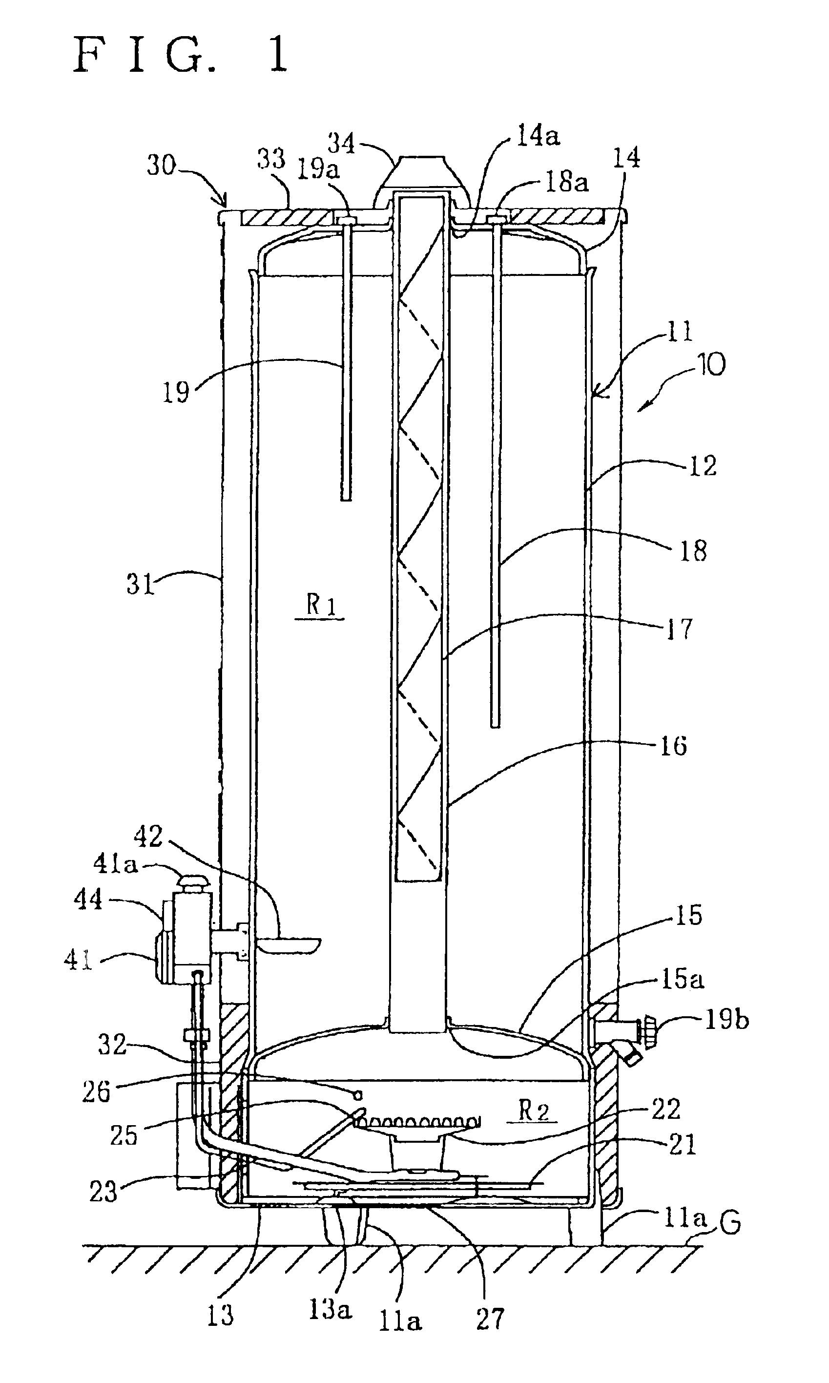
[0039]Next, as one embodiment of the present invention will be described with reference to the drawings, FIG. 1 is an elevational view in section showing a water heater with a flame arrester (hereinafter, referred to as only water heater) of the first invention. This water heater 10 is provided with a body 11 which is made of iron, closed on the ends of top and bottom portions of the hollow cylindrical shape and whose interior surface is covered with enamel, an outer case 30 which covers the outer peripheral and upper surface of the body 11, and a controller 41 for controlling an operation of the water heater 10.

[0040]The body 11 of the water heater 10 is provided with cylindrical portion 12, bottom plate portion 13 which is a flat plate for closing the end of the lower portion, an upper end plate 14 which is slightly swelled upward in a spherical shape and closes the end of the upper portion, and the body 11 is provided in a state where it stands on the floor surface G with legs 11...

second embodiment

[0053]Next, the present invention will be described below with reference to FIG. 6 and FIG. 7.

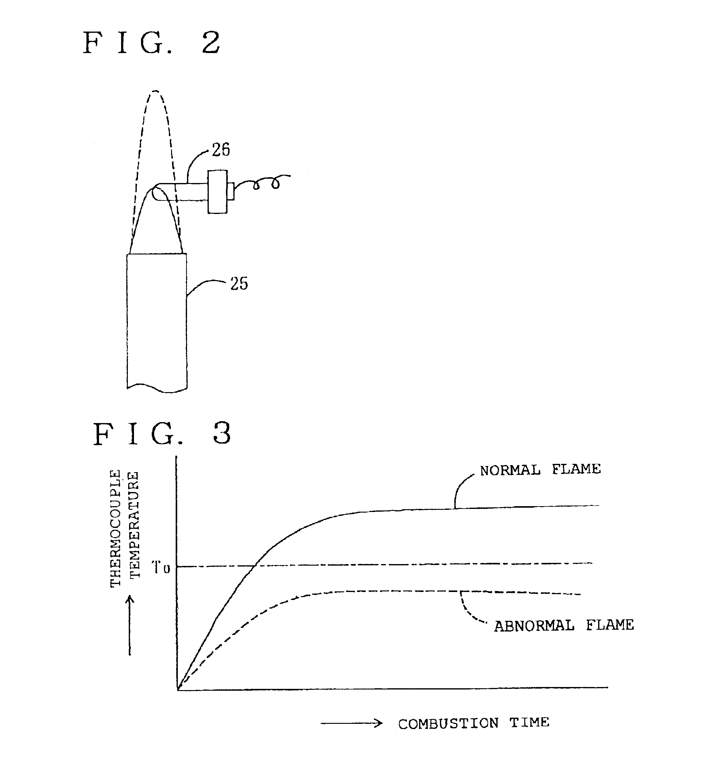
[0054]In the second embodiment of the first invention, it is made so that the clogging state of the flame arrester 27 can be detected by the shape of the pilot burner and the electromagnetic valve built in the controller 41 can be closed according to the state of clogging. Specifically, the pilot burner is used as detection means for detecting the clogging of the flame arrester 27. The pilot burner 50 is, as shown in FIG. 6, a hollow cylindrical body 51, whose end is a cone-shaped projecting portion 52 projecting in an axial direction. A port for heating thermocouple 53 is provided on the side wall nearby the projecting portion 52 of the cylindrical body 51, a port for carrying over 54 is provided on the projecting portion 52. Moreover, the cylindrical body 51 is provided with air supply holes 55 nearby the connection portion with the gas supply pipe 58, over which wire gauze 56 covers and ...

third embodiment

[0057]Next, the first invention will be described below with reference to FIG. 9.

[0058]In the third embodiment, as detection means for detecting a state of flame, the sensor burner 60 which is capable of securely detecting a state of flame is used with the pilot burner. The sensor burner 60 is mounted on a gas draft pipe 69 branched off from the gas supply pipe 68 described later, and comprises the mixture pipe 61 approximately L-letter shaped, a porous plate 63a having ports, a cylindrical guard 63 surrounding the porous plate 63a, and a thermocouple 64. The mixture pipe 61 is provided with a nozzle 62 connected to the gas draft pipe at the end, and the porous plate 63a having ports provided inwardly in the axial direction and the cylindrical guard 63 surrounding the porous plate 63a are provided at the other end of the mixture pipe 61. The thermocouple 64 is provided nearby the outside of the porous plate 63a and arranged to penetrate the wall of the cylindrical guard 63. Moreover...


PUM


Abstract

A water heater is arranged with the hot water storage chamber R1 at the top and the combustion chamber R2 at the bottom within the body 11 which is a container. The combustion chamber R2 is equipped with the air supply inlet 13a, and the flame arrester 27 is provided at the air supply inlet 13a. Within the combustion chamber R2, the main burner 22 and the pilot burner 25 are provided, the changing state of flame of the pilot burner 25 is detected by the thermocouple 26, and a controller 41 closes an electromagnetic valve for opening and closing the main gas passage, stops the combustion of the main burner 22 as well, and rings the alarm 44. In a alternate embodiment, a sensor burner 60 is used as a safety device to detect a state of flame of the sensor burner and to shut off fuel to the main gas burner.

Description

[0001]This application is a Division of U.S. application Ser. No. 09 / 834,535, filed Apr. 13, 2001 now U.S. Pat. No. 6,561,138.BACKGROUND OF THE INVENTION[0002]1. Field of the Invention[0003]The present invention relates to a water heater with a flame arrester set in a garage, a cellar, a warehouse and the like where inflammable materials such as gasoline, thinner, benzine and the like generating combustible vapor are stored.[0004]2. Description of the Related Art[0005]Conventionally, in this kind of a water heater with a flame arrester, for example, as shown in FIG. 19, a hot water storage chamber 2 and a combustion chamber 3 are provided upward and downward within a hollow cylindrical body 1, the combustion chamber 3 is provided with an exhaust passage 5 which penetrates the shaft center position and has an air supply inlet 4 and an opening on the upper portion of the body 1 for exhausting combustion gas within the combustion chamber 3, and further, a flame arrester (flame interrup...

Claims


Application Information

Patent Timeline
IPC IPC(8): F23D14/46F23D14/68F23D14/72F24H1/20
CPCF23D14/68F23D14/72F24H1/205F23M2900/11021F23D2208/10
Inventor KOBAYASHI, TOSHIHIROCHIKAZAWA, HIDEOKODAMA, MASARU
Owner PALOMA
Learn More