
Shift-lever apparatus of an automatic transmission for enabling manual mode operation

a technology of automatic transmission and shift lever, which is applied in the direction of manual control with single controlling member, mechanical control devices, instruments, etc., can solve the problems of increasing manufacturing costs, complex structure of the mechanism, and insatiable drivers of the automatic transmission shift speed, etc., to achieve the effect of reducing the relative movemen

Inactive Publication Date: 2005-05-24
HYUNDAI MOTOR CO LTD
View PDF12 Cites 19 Cited by
  • Summary
  • Abstract
  • Description
  • Claims
  • Application Information

AI Technical Summary

Benefits of technology

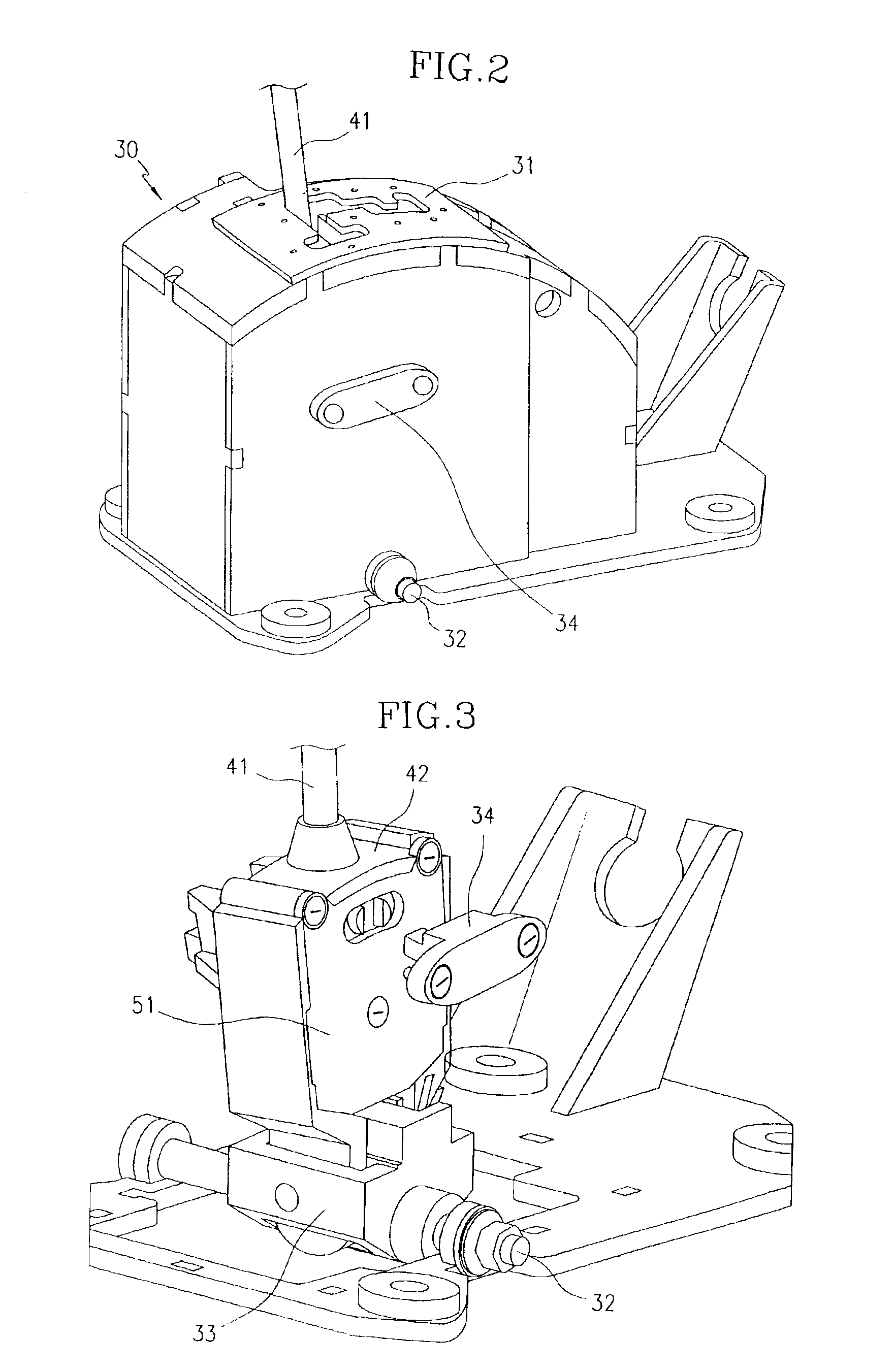
[0007]Another exemplary shift-lever apparatus useful with the present invention includes: a housing; a shift-lever rotatably mounted to the housing, being rotatable in a predetermined direction; a base member fixed to the shift-lever; first and second switches fixed to the base member apart from each other in the predetermined direction; a pressing member mounted on the base member between the first and second switches such that the pressing member can move relative to the base member; an elastic member, abutted by both the pressing member and the base member, for providing restoring force to diminish the relative movement between the pressing member and the base member; and a locking member for limiting a relative movement between the pressing member and the housing.

Problems solved by technology

Only common driving conditions are taken into consideration in current shift-patterns, and therefore, in some situations the shift-speed automatically engaged by the automatic transmission is not satisfactory to a driver.
Although a lot of research on shift-patterns has taken place to minimize the occurrence of inappropriate shifting in such situations, new shift-patterns do not always satisfy every driver.
Current mechanisms for enabling manual mode operation of an automatic transmission contain a plurality of un-modularized components, which makes the structure of these mechanisms complex and increases manufacturing costs.

Method used


Image

  • Shift-lever apparatus of an automatic transmission for enabling manual mode operation
  • Shift-lever apparatus of an automatic transmission for enabling manual mode operation
  • Shift-lever apparatus of an automatic transmission for enabling manual mode operation

Examples


Embodiment Construction

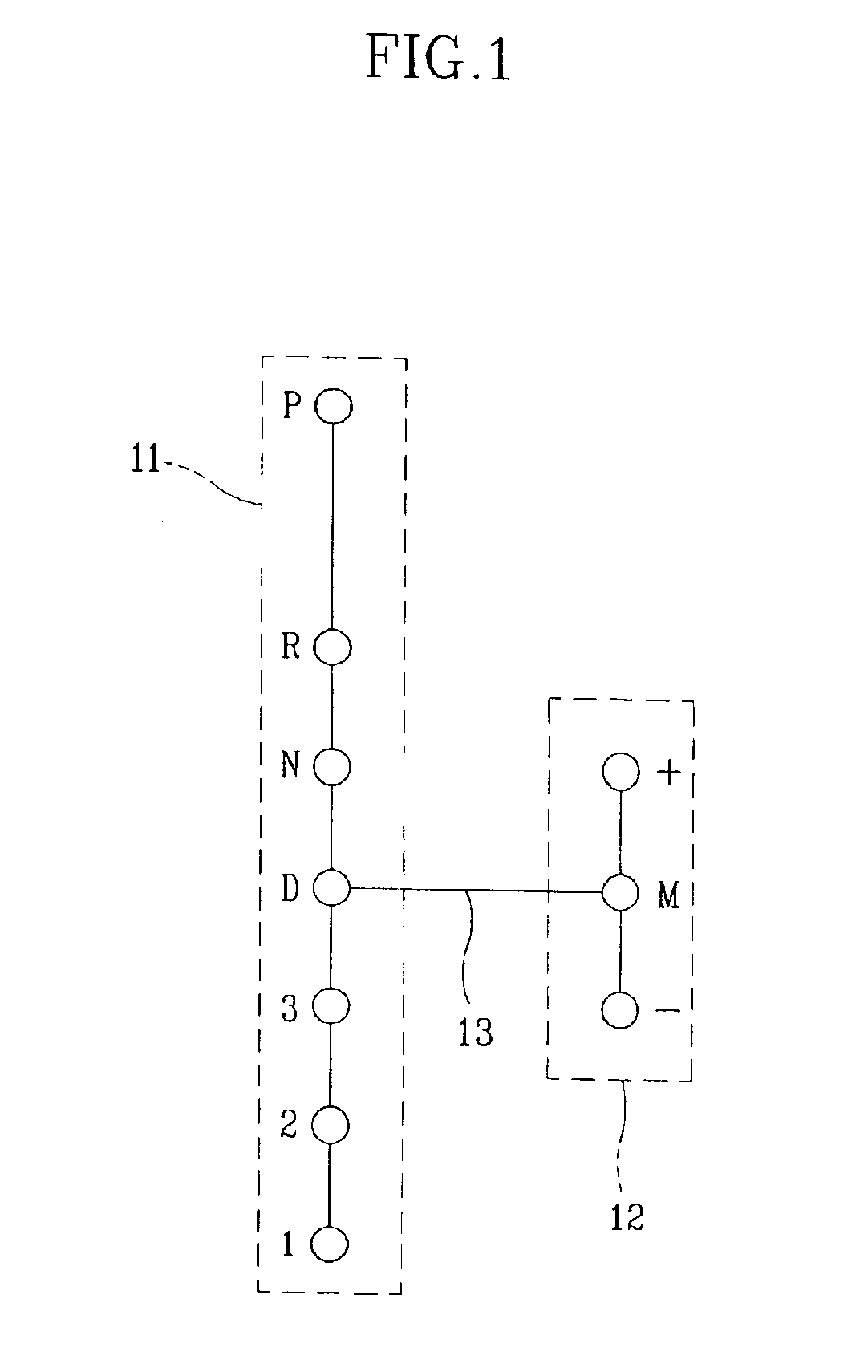
[0016]As shown in FIG. 1, a shift-lever apparatus for an automatic transmission provided with such a manual-mode function is provided with a manual-shift column 12. The manual-shift column 12 is connected to an ordinary shift column 11. Usually the manual shift column 12 is aligned in parallel with the ordinary shift column 11 and connected to the same at a “D” shift-lever position by a gate (usually called a manual gate) 13.

[0017]If a shift lever is located at the “D” position, the automatic transmission changes shift-speeds according to predetermined shift patterns, however, if the shift lever is moved to the manual shift column 12, the automatic transmission changes shift-speeds according to a driver's manual shifting. For example, the gears are upshifted when the shift lever is moved to the “+” position, or downshifted when the shift lever is moved to the “−” position. The requests for upshifting and downshifting are sensed by manual mode switches.

[0018]Referring to FIG. 2, a sh...


PUM


Abstract

The shift-lever apparatus of an automatic transmission for enabling manual mode operation includes a housing, a shift-lever connected to a rotating unit disposed at a lower portion of the housing such that the shift-lever can rotate about the rotating unit, and a base member fixed to the shift-lever and enclosed by the housing, such that the base member moves according to the movement of the shift-lever. The apparatus also includes “+” and “−” switches, each being disposed at either side of the base member, such that the “+” and “−” switches are selectively operated according to the movement of the shift-lever. Finally, the apparatus includes a switch operating unit disposed at the base member such that the switch operating unit selectively presses the “+” and “−” switches.

Description

FIELD OF THE INVENTION[0001]The present invention relates to a shift-lever apparatus of an automatic transmission for enabling manual mode operation, and more particularly, to a shift-lever apparatus whose switch-operating mechanism is modularized.BACKGROUND OF THE INVENTION[0002]In general, an automatic transmission automatically changes shift-speed based on driving circumstances according to predetermined shift-patterns. Only common driving conditions are taken into consideration in current shift-patterns, and therefore, in some situations the shift-speed automatically engaged by the automatic transmission is not satisfactory to a driver. Although a lot of research on shift-patterns has taken place to minimize the occurrence of inappropriate shifting in such situations, new shift-patterns do not always satisfy every driver. Accordingly, a manual mode for an automatic transmission has been introduced. This manual mode enables manual shifting by sensing a driver request to shift spe...

Claims


Application Information

Patent Timeline
IPC IPC(8): F16H59/02G05G9/06G05G9/10G05G9/00B60K20/02F16H61/28
CPCF16H59/0204G05G9/06G05G9/10Y10T74/2003Y10T74/20085Y10T74/20067Y10T74/20159F16H2059/0239B60K20/02
Inventor CHO, YANG-RAE
Owner HYUNDAI MOTOR CO LTD
Learn More