
Liquid crystal display device

a display device and liquid crystal technology, applied in the field of liquid crystal display devices, can solve the problems of difficult inclusion and fixation of lines in the lcd module, and achieve the effect of thin and lighter lcd devices

Inactive Publication Date: 2005-05-17
SAMSUNG DISPLAY CO LTD
View PDF8 Cites 19 Cited by
  • Summary
  • Abstract
  • Description
  • Claims
  • Application Information

AI Technical Summary

Benefits of technology

[0031]The present invention has been made to solve the aforementioned problem, and accordingly it is an object of the present invention to provide a LCD device in which a total size and a weight can be reduced.
[0032]It is another object of the present invention to provide a LCD device in which a size can be minimized by using a support for rigidly making an installation of the LCD device.
[0042]Accordingly, it is possible to manufacture the LCD device in which the edge except for a region, in which the analog / digital board and the inverter board are mounted, has the same thickness as the LCD module. By minimizing a total thickness of the LCD device, the thinner and lighter LCD device can be obtained.

Problems solved by technology

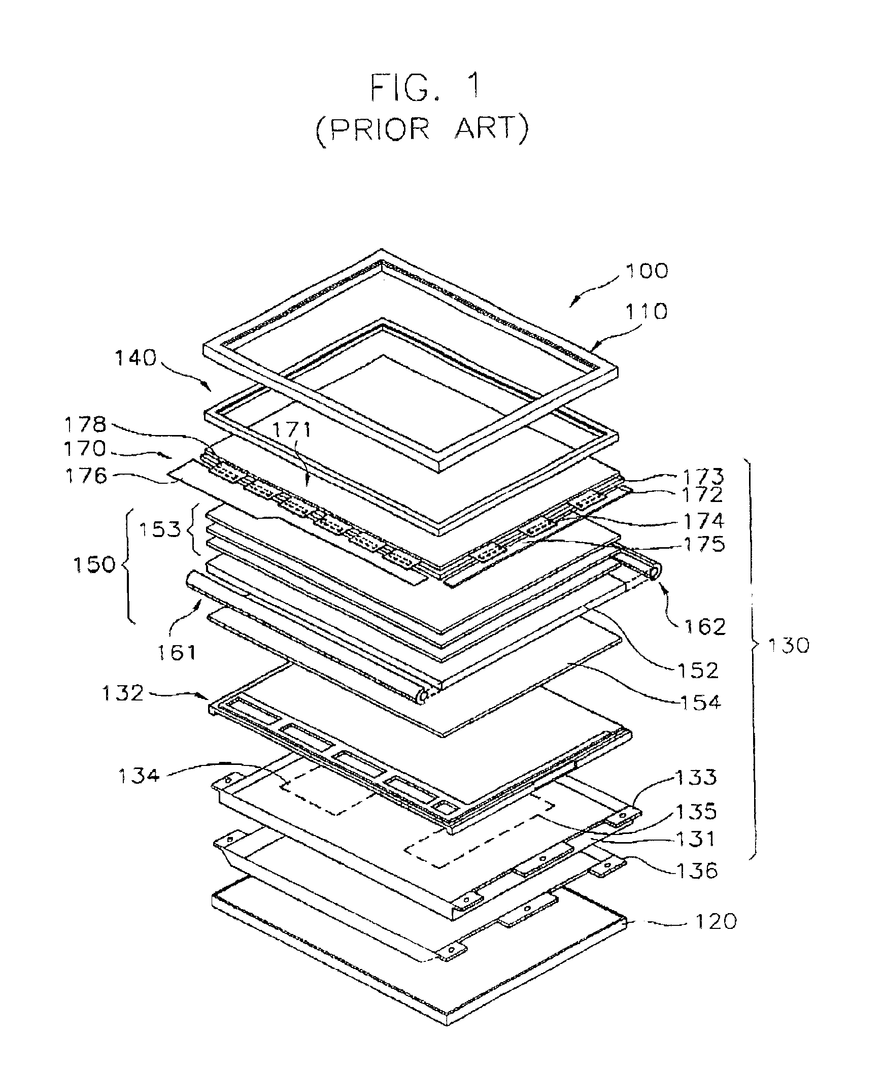
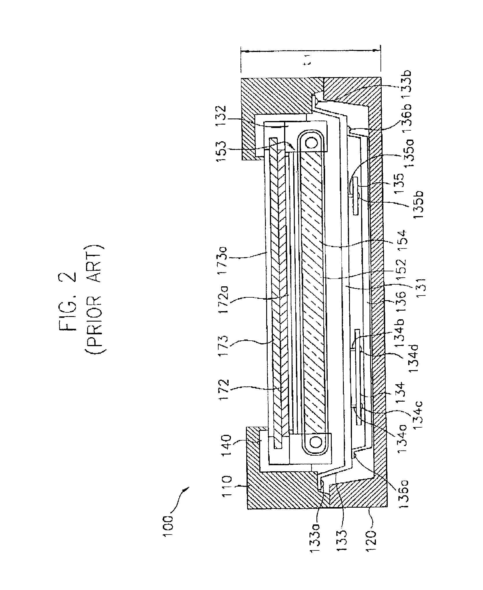
In the conventional LCD device, there are many problems as follows.
Furthermore, when the line for supplying the power and the line for transferring the signals are longer, it becomes difficult to include and to fix the lines to the LCD module 130 in a stable fashion.

Method used


Image

  • Liquid crystal display device
  • Liquid crystal display device
  • Liquid crystal display device

Examples


Embodiment Construction

[0057]Hereinafter, LCD devices according to the preferred embodiments of the present invention will be described in detail with reference to the accompanying drawings.

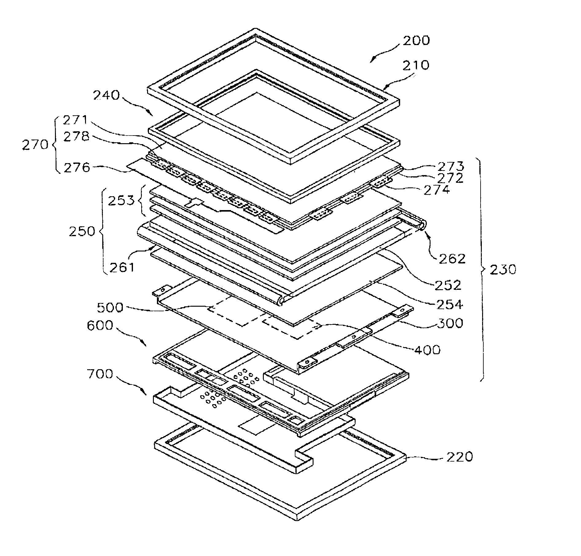
[0058]FIG. 5 is an exploded perspective view schematically showing a LCD device according to a preferred embodiment of the present invention.

[0059]Referring to FIG. 5, the LCD device 200 includes a LCD module 230 for displaying an image when an image signal is applied thereto and a case that has front and rear cases 210 and 220, for receiving the LCD module 230.

[0060]The LCD module 230 can be generally and functionally divided into a section for displaying the image, a receiving container for receiving the displaying section and a section for controlling an operation of the displaying section.

[0061]Particularly, the displaying section has a display unit 270 including a LCD panel 271 and a backlight assembly 250 for supplying a light to the display unit 270. The receiving container has a bottom chassis 300 for receiving...


PUM

PropertyMeasurementUnit
widthaaaaaaaaaa
areaaaaaaaaaaa
flexibleaaaaaaaaaa

Abstract

Disclosed are a liquid crystal display (LCD) device and a method for assembling the LCD device. The LCD device has a display section for displaying images, a receiving container for receiving the display section, a power supplying section for supplying a power source to the display section, a signal converting section for converting signals from the display section and a securing section for securing the power supplying section and the signal converting section to the receiving container. The power supplying section and the signal converting section are disposed between the display section and the securing section that is directly facing to a rear surface of the receiving container. Accordingly, a total thickness and weight of the LCD device can be minimized and an assembly facility of the LCD device can be improved

Description

BACKGROUND OF THE INVENTION[0001]1. Field of the Invention[0002]The present invention relates to a liquid crystal display device (LCD), and more particularly, to a LCD device of which a size and a weight are reduced.[0003]2. Description of the Related Art[0004]In recent times, information processing devices continue to rapidly develop with various architectures, functions and faster information processing speed. Information processed in these information processing devices has an electrical signal format. In order to visually confirm information processed in the information processing device, a display as an interface should be provided.[0005]Recently, a LCD device that is lighter, and smaller than a CRT type display device has been developed. The LCD device has a full color displaying function and a high resolution. As a result, the LCD device is widely used as a monitor of a computer, a television, and another display device.[0006]The LCD device applies a voltage to a predetermine...

Claims


Application Information

Patent Timeline
Patent Type & Authority Patents(United States)
IPC IPC(8): G02F1/13G02F1/1333G02F1/1345G09F9/00G09F9/35
CPCG02F1/133308G02F1/133615G06F1/1601G06F2200/1612G02F1/133314G02F1/133334G02F1/133612G02F1/1333G02F1/13452G02F1/133608G02F1/133512
Inventor HA, JIN-HOCHANG, SE-IN
Owner SAMSUNG DISPLAY CO LTD
Learn More