Bayonet base for lamp mount

Inactive Publication Date: 2005-05-17
PATENT TREUHAND GESELLSCHAFT FUR ELECTRIC GLUEHLAMPEN MBH
View PDF6 Cites 16 Cited by
  • Summary
  • Abstract
  • Description
  • Claims
  • Application Information

AI Technical Summary

Benefits of technology

[0003]The object of the present invention is thus to design lamps with a reduced packaging volume.
[0009]In order to avoid the risk of electric shock which exists when the bayonet adapter is rotated into a lampholder, the contact locations should be concealed in the noses such that they usually cannot be touched. A first measure makes this possible in that the contact wires in the noses are only accessible from the outside in small slots on the rear side of the nose, as seen in the plug-in direction of the bayonet connector. This, for the most part, does away with the risk of open contact locations being touched.
[0010]In order for the risk of electric shock to be curbed further, the slots for the contacts may be provided with integrally molded coverings which, upon rotation into the bayonet bushing, break off and thus expose the contact slots. It is advantageous here if each slot covering has a lamellar extension or a lug in the direction of the cylinder axis of the main portion, by way of which the slot covering can be readily broken off during rotation of the bayonet components.
[0011]The bayonet bushing essentially comprises a base plate with a bore which is adjoined by at least one groove, usually two grooves. For the contact-connection with contact locations of the noses of the bayonet connector, contact bridges are arranged tangentially outside the bore and within the circle which is determined by the radius from the center of the bore to the distal end of a groove. This arrangement makes it possible for the contact locations to be rotated onto the contact bridges by the rotation of the bayonet closure, the electrical connection being produced as a result.
[0014]For reasons of avoiding the risk of electric shock, the bayonet adapter should be rotated into the bayonet counterpart of the lamp mount such that it cannot be removed. This can be realized by latching hooks which are fitted on the bayonet connector or the bayonet bushing. This makes it possible to prevent removal once mounting has taken place, which in particular has the advantage that the slot coverings broken off for contact-connection purposes are no longer openingly accessible.

Problems solved by technology

Since the E27 base is arranged perpendicularly to the direction or plane in which the respective tubular fluorescent lamp extends, comparatively bulky packaging has to be provided for the tubular fluorescent lamps.

Method used


Image

  • Bayonet base for lamp mount
  • Bayonet base for lamp mount
  • Bayonet base for lamp mount

Examples


Embodiment Construction

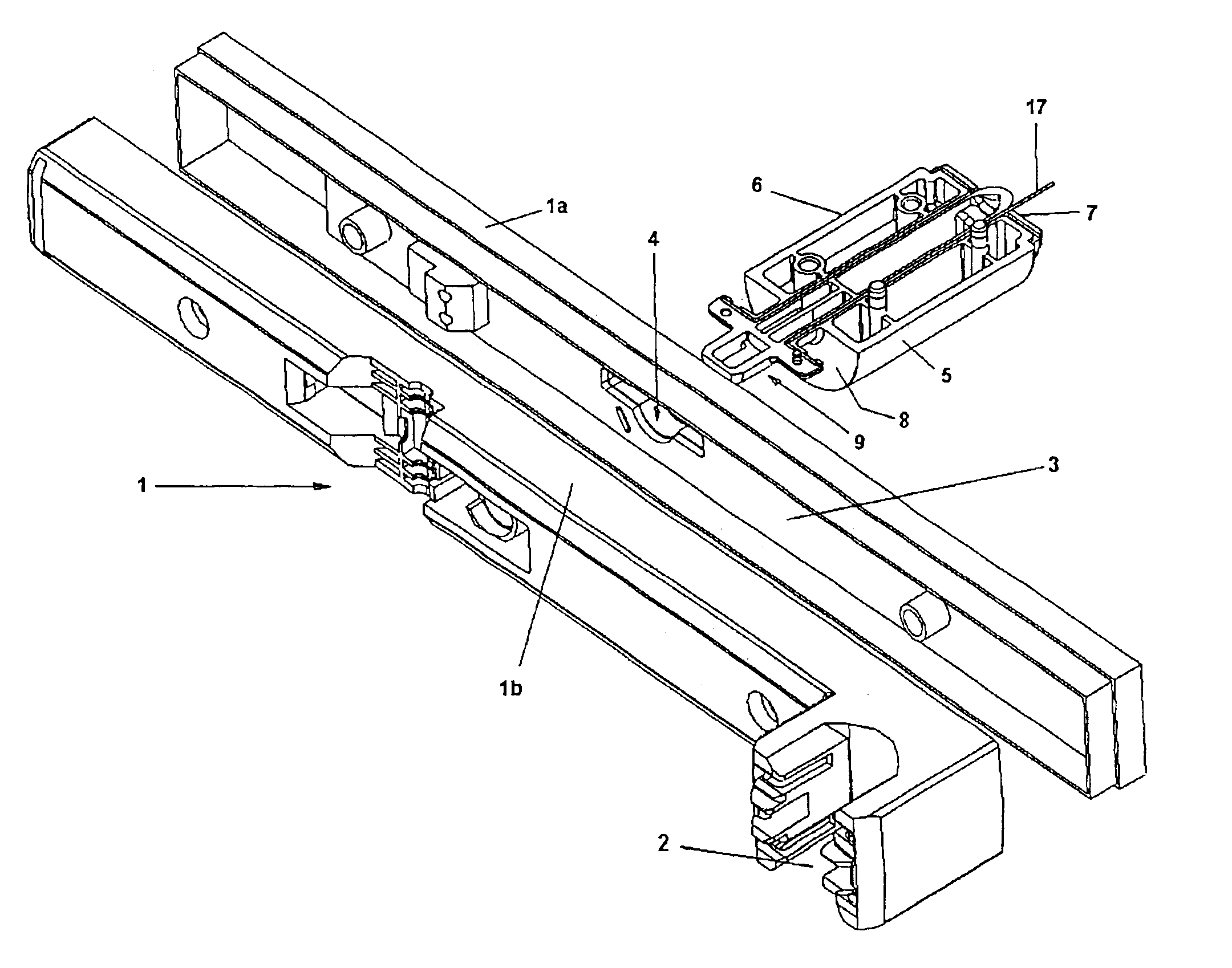
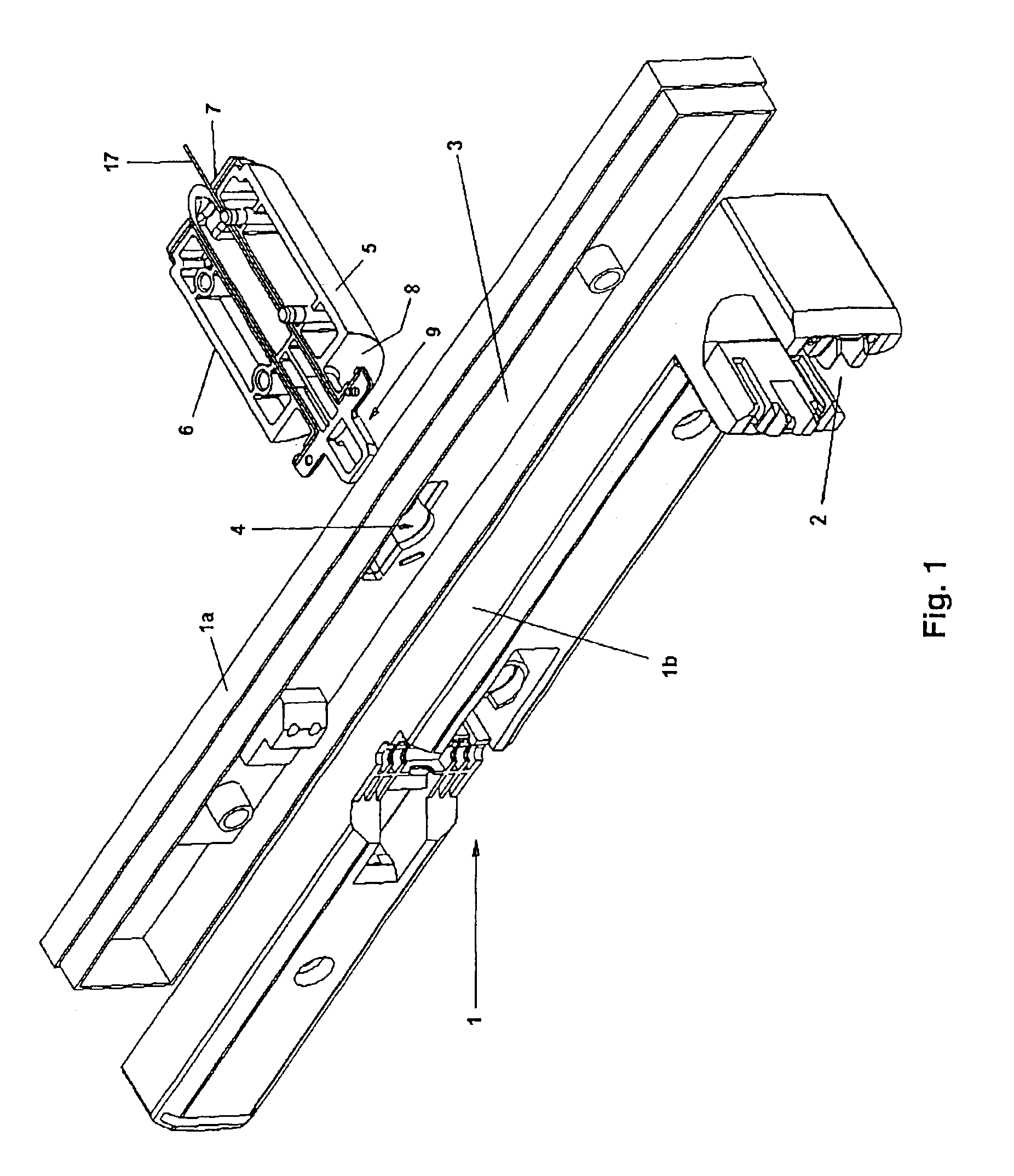
[0019]FIG. 1 represents a lamp mount 1 with two enclosure halves 1a and 1b in an exploded illustration. The top enclosure half 1b has a holder 2 into which a toroidal tubular fluorescent lamp (not illustrated) can be plugged in from above. The tubular fluorescent lamp has a torus diameter which corresponds to the longitudinal dimension of the lamp mount 1. In the bottom enclosure half 1a of the lamp mount 1, an electrical ballast (not illustrated) is accommodated on a printed circuit board 3. Furthermore, a bayonet bushing 4 is provided in the housing of the lamp mount 1. A bayonet connector 9 of a bayonet adapter 5 can be plugged into this bayonet bushing 4 and latched in by rotation. FIG. 1 merely illustrates half of the bayonet connector 9 of the bayonet adapter 5, it being possible for the bayonet connector to be joined together from injection-molded halves. The bayonet adapter 5 has an essentially cylindrical body 6. It is possible for a lamp base (not illustrated), e.g. an E27...


PUM


Abstract

Lamp mounts for tubular fluorescent lamps with a screw base are to be configured in a more compact manner for packaging purposes. A bayonet adapter (5) which can be rotated into a lamp mount (1) is provided for this purpose. The bayonet adapter (5) has, for example, an E27-type screw base opposite the bayonet connector (9). Since the bayonet adapter (5) can be removed from the lamp mount (1), a corresponding luminaire can be packaged in a more compact manner.

Description

TECHNICAL FIELD[0001]The present invention relates to a bayonet adapter and, in particular, to a bayonet base for illumination means. The present invention also relates to a lamp mount having a retaining device for bearing an illumination means and for the electrical contact-connection of the illumination means.BACKGROUND ART[0002]In addition to conventional incandescent lamps with an E27-type lamp base, for example toroidal or elongate tubular fluorescent lamps with an E27 base are also available. An electrical ballast (EVG) is also integrated here in the lamp mount of the tubular fluorescent lamps. Since the E27 base is arranged perpendicularly to the direction or plane in which the respective tubular fluorescent lamp extends, comparatively bulky packaging has to be provided for the tubular fluorescent lamps.DISCLOSURE OF THE INVENTION[0003]The object of the present invention is thus to design lamps with a reduced packaging volume.[0004]This object is achieved according to the inv...

Claims


Application Information

Patent Timeline
IPC IPC(8): F21V19/00H01R33/00H01R33/945
CPCH01R33/9456F21V19/0075
Inventor SCHADHAUSER, KLAUS
Owner PATENT TREUHAND GESELLSCHAFT FUR ELECTRIC GLUEHLAMPEN MBH
Why Eureka
Try Eureka