
Method and apparatus for reducing dynamic range of a power amplifier

a power amplifier and dynamic range technology, applied in the direction of simultaneous amplitude and angle modulation, gain control, modulation, etc., can solve the problem of reducing the dynamic range generating more noise, and difficult to meet the dynamic range requirements of umts power amplifiers. problem, to achieve the effect of reducing the dynamic range of a power amplifier

Inactive Publication Date: 2005-05-10
TELEFON AB LM ERICSSON (PUBL)
View PDF19 Cites 76 Cited by
  • Summary
  • Abstract
  • Description
  • Claims
  • Application Information

AI Technical Summary

Benefits of technology

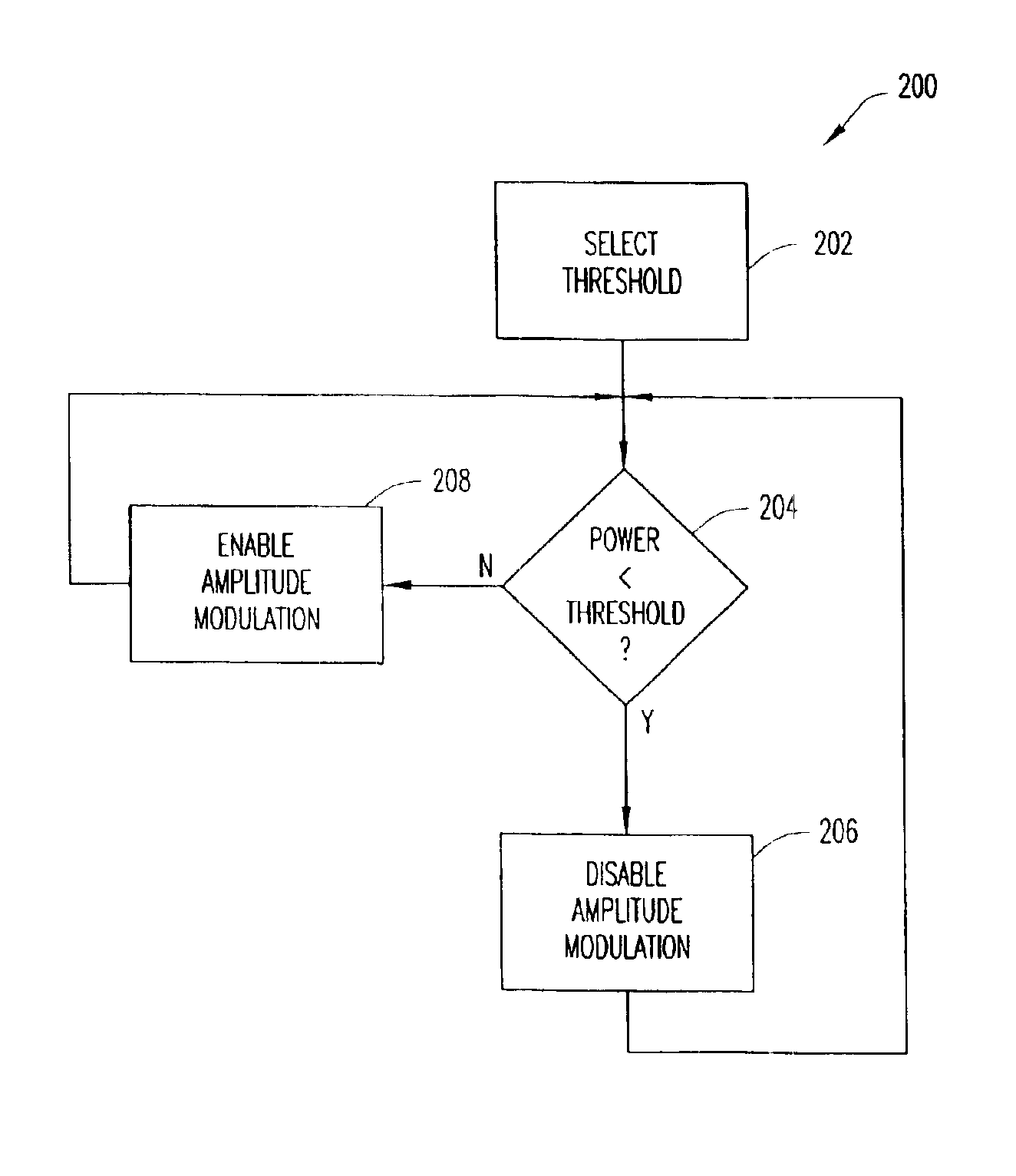
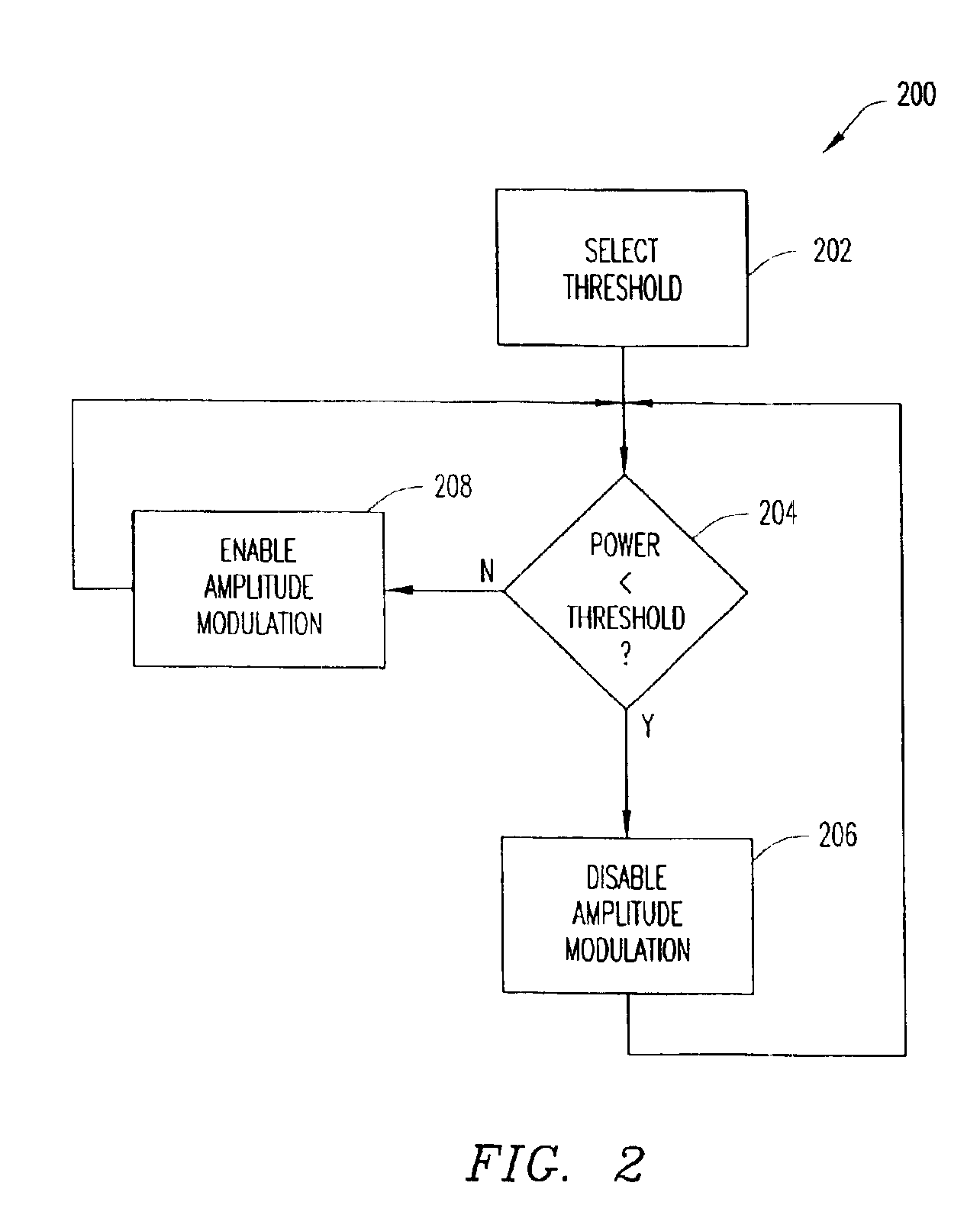
The present invention provides an apparatus and method for reducing the dynamic range of a power amplifier. This is achieved by performing phase modulation of an input signal and then amplifying it based on the output power of the apparatus. The output-power threshold is selected to ensure that at least one signal requirement is not outside a pre-determined range. This invention allows for more efficient and reliable transmission of signals with reduced dynamic range requirements.

Problems solved by technology

Running the blocks in the linear mode causes the power efficiency of the transmitter to drop and results in more noise being generated.
For example, the UMTS power-amplifier dynamic-range requirements are especially difficult to meet.

Method used


Image

  • Method and apparatus for reducing dynamic range of a power amplifier
  • Method and apparatus for reducing dynamic range of a power amplifier
  • Method and apparatus for reducing dynamic range of a power amplifier

Examples


Embodiment Construction

[0016]In UMTS, the dynamic range of a power amplifier is defined as a range in dB in which all required UMTS specification points (i.e., signal requirements) are met. For example, for a UMTS user equipment (UE) of power class 4, the output power range must be from −50 dBm to 24 dBm (i.e., 74 dB). A UMTS-required modulation depth must then also be added to the output power range to obtain the minimal acceptable dynamic range of the power amplifier.

[0017]The modulation depth is defined as a ratio of the maximal and minimal envelope of the transmitted signal. A phase-modulated signal includes no amplitude information; therefore, the modulation depth is 0 dB. An amplitude-modulated (AM) signal has all information stored in the envelope; therefore, the modulation depth is greater than 0 dB and is infinite in the case of a 100% AM signal. The modulation depth is ideally infinite. However, UMTS spectrum-emission-mask signal requirements are the limiting factor in determining a minimal acce...


PUM


Abstract

An output-power threshold is selected such that one or more signal requirements is not outside a pre-determined range when output power of a polar transmitter is less than the output-power threshold. A determination is made whether the output power is less than the threshold. In response to a determination that the output power is less than the threshold, amplitude modulation of a polar signal transmitted by the polar transmitter is disabled. When the output power meets or exceeds the output-power threshold, the polar signal transmitted by the polar transmitter is both amplitude and phase modulated.

Description

BACKGROUND OF THE INVENTION[0001]1. Technical Field of the Invention[0002]The present invention generally relates to reducing a dynamic range of a power amplifier. In particular, the present invention relates to reducing a dynamic range of a power amplifier used as part of a polar transmitter while still meeting all other transmitter signal requirements.[0003]2. Description of Related Art[0004]Many communication-system standards such as, for example, the Global System for Mobile Communications (GSM), use constant-envelope modulation. In constant-envelope modulation, all modulating information is contained in a phase part of a transmitted signal. As a result, all blocks of a modulator used as part of a GSM transmitter can be run in saturation.[0005]Many newer communication-system standards require linear modulation. Linear modulation is more spectrally-efficient than constant-envelope modulation. Systems based on, for example, Enhanced Data for GSM Evolution (EDGE), Universal Mobile ...

Claims


Application Information

Patent Timeline
Patent Type & Authority Patents(United States)
IPC IPC(8): H03C3/00H03C5/00H03C3/09
CPCH03C3/0925H03C5/00H03C3/0933
Inventor NILSSON
Owner TELEFON AB LM ERICSSON (PUBL)
Learn More