
Variable-resistance element

a resistance element and variable technology, applied in the direction of resistor details, resistor manufacturing, resistors with sliding contact, etc., can solve the problems of high wear resistance and longer operating life, poor microlinearity, and the surface of resistors that require, so as to prolong the sliding lifetime of the resistor as a whole, the effect of easy planarization

Inactive Publication Date: 2005-05-10
ALPS ALPINE CO LTD
View PDF10 Cites 5 Cited by
  • Summary
  • Abstract
  • Description
  • Claims
  • Application Information

AI Technical Summary

Benefits of technology

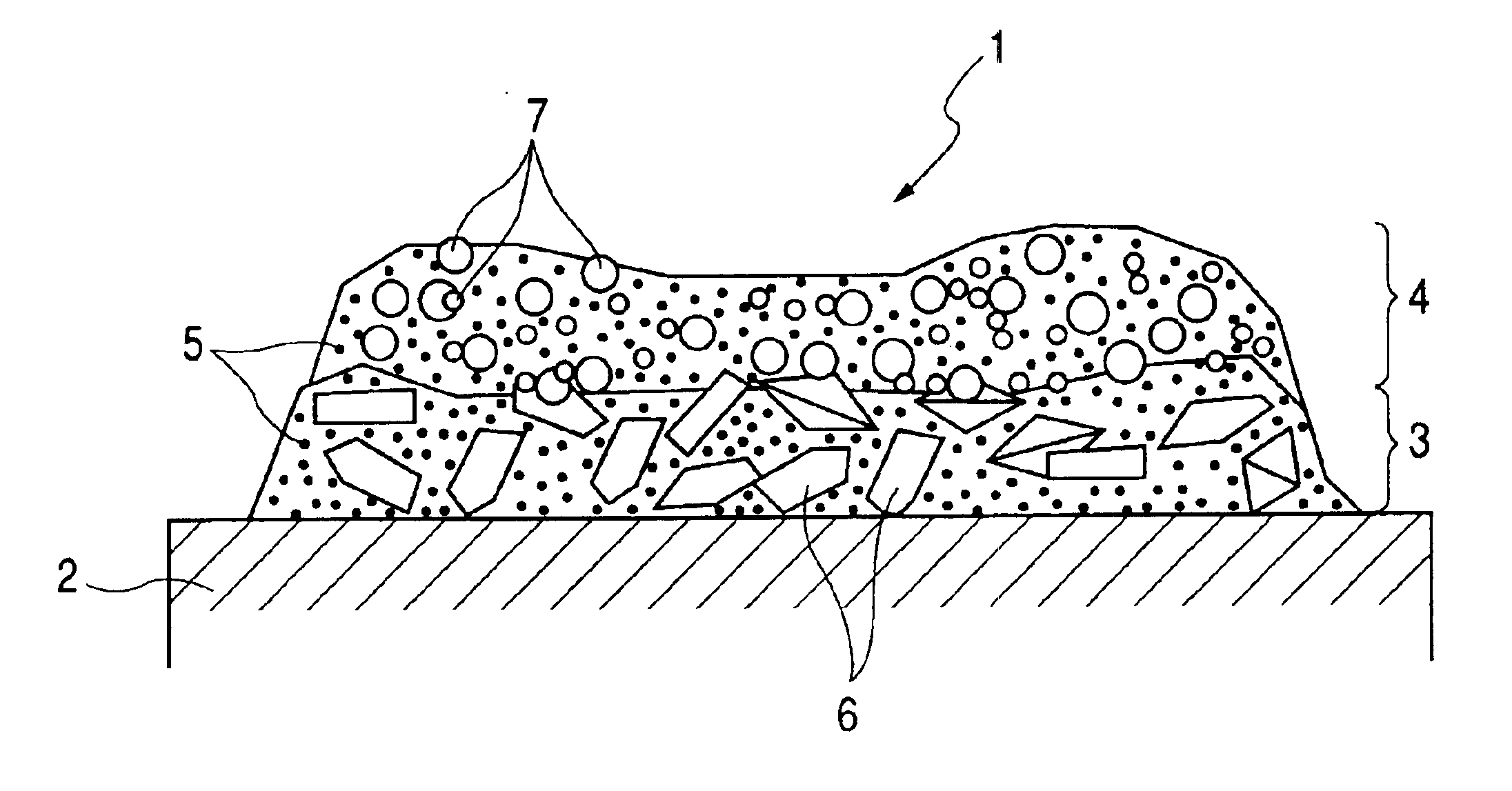
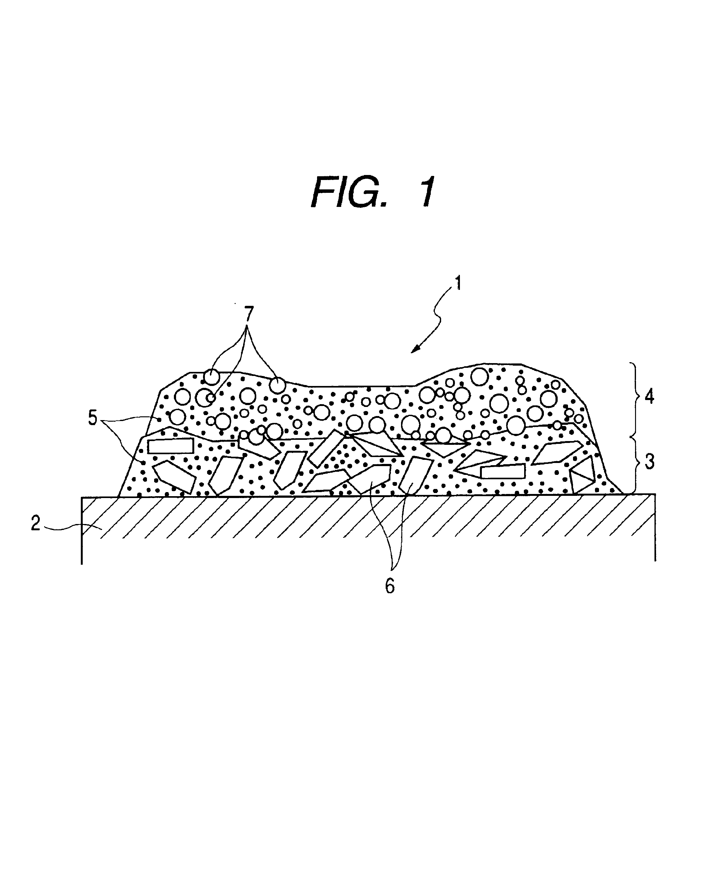
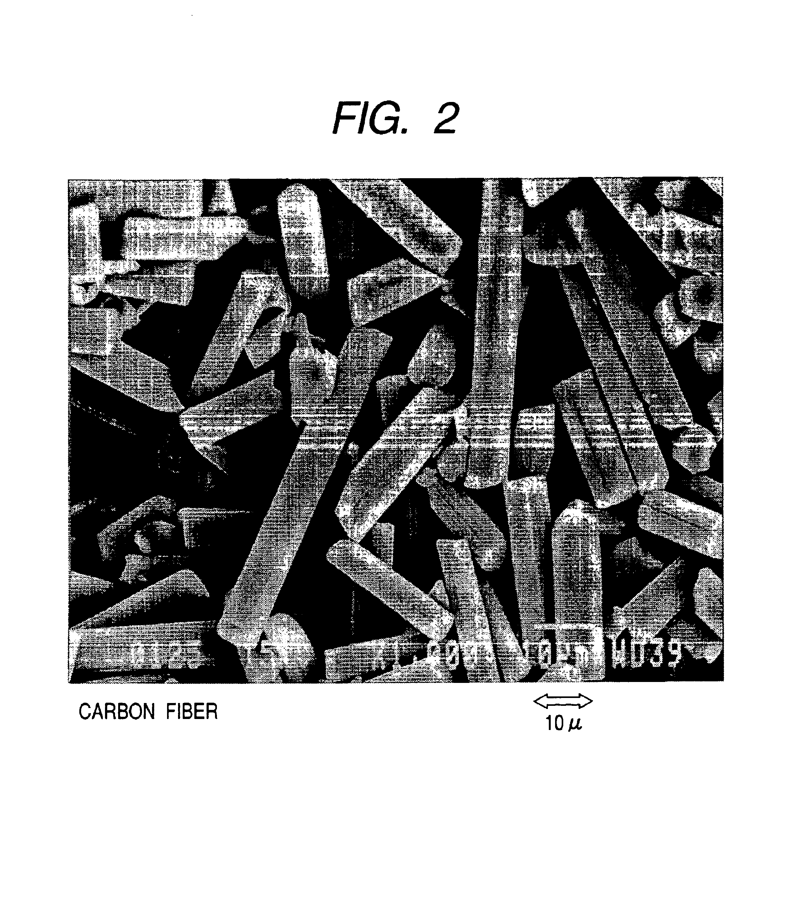
The present invention provides a variable-resistance element with high wear resistance, longer operating lifetime, and superior microlinearity. This is achieved by using a resistor with two layers of reinforcing material dispersed in a binder resin. The second layer of reinforcing material has smaller particles, resulting in a smoother surface and improved microlinearity. The amount of second reinforcing material should be between 5-30% by volume to achieve optimal results. The first layer of reinforcing material should have an average particle size between 1-10 μm to ensure proper sliding lifetime and microlinearity. The first reinforcing material should be pulverized carbon fibers.

Problems solved by technology

Variable-resistance elements having a sliding contact moving on a surface of a resistor require high wear resistance and longer operating life.
Thus, the roughness of the surface of the resistor in terms of arithmetic average becomes larger, resulting in poor microlinearity.

Method used


Image

  • Variable-resistance element
  • Variable-resistance element
  • Variable-resistance element

Examples


example

Example 1

[0053]The first resistor paste and the second resistor paste were prepared according to the compositions shown in Tables 1 and 2 below.

[0054]

TABLE 1First Resistor PasteParticleComponentMaterialWeight [g]size [μm]BinderPhenolic resin387—resinConductiveCarbon black930.04material(acetylene black)FirstPulverized carbon1263reinforcingfibersmaterial 6SolventCarbitol394—

[0055]

TABLE 2Second Resistor PasteParticleComponentMaterialWeight [g]size [μm]BinderPhenolic resin433—resinConductiveCarbon black730.04material(acetylene black)SecondThermal black810.35reinforcingmaterial 7SolventCarbitol413—

[0056]The first resistor paste for forming the first resistive layer 3 was applied, by printing using a screen of an appropriate mesh, on an epoxy glass insulating substrate 2 having silver electrodes preliminarily formed thereon. The applied paste was dried to form the first resistive layer 3. The second resistor paste for forming the second resistive layer 4 was then applied on the first resi...

example 2

[0059]A resistor of Example 2 was prepared as in Example 1 except that the thermal black (average particle size: 0.35 μm) used as the second reinforcing material 7 of the second resistor paste shown in Table 2 was replaced with 81 grams of carbon black having an average particle size of 0.12 μm.

example 3

[0060]A resistor of Example 3 was prepared as in Example 1 except that the thermal black (average particle size: 0.35 μm) used as the second reinforcing material 7 of the second resistor paste shown in Table 2 was replaced with 81 grams of pulverized carbon black having an average particle size of 0.90 μm (measured by laser diffractometry).


PUM

PropertyMeasurementUnit
particle sizeaaaaaaaaaa

Abstract

A variable-resistance element exhibiting high wear resistance and superior microlinearity includes a resistor constituted from a first resistive layer containing a first reinforcing material and a second resistive layer containing conductive carbon black and a second reinforcing material, the second resistive layer being disposed on the first resistive layer. The first reinforcing material is pulverized carbon fibers having an average particle size of 3 μm. The second reinforcing material is thermal black having an average particle size of 0.35 μm.

Description

BACKGROUND OF THE INVENTION[0001]1. Field of the Invention[0002]The present invention relates to a variable-resistance element (or device), the resistance of which is changed by a sliding contact moving on a surface of a resistor. In particular, it relates to a variable-resistance element having superior microlinearity.[0003]2. Description of the Related Art[0004]Variable-resistance elements having a sliding contact moving on a surface of a resistor require high wear resistance and longer operating life. Examples of conventional variable-resistance elements are disclosed in Japanese Unexamined Patent Application Publication No. 3-233904 and Japanese Patent No. 2889792 (corresponding to U.S. Pat. No. 5,475,359).[0005]The variable-resistance element disclosed in Japanese Unexamined Patent Application Publication No. 3-233904 includes a resistor prepared by applying, by means of screen-printing, a resist paste composed of carbon black and carbon fibers dispersed in resin. Hard carbon f...

Claims


Application Information

Patent Timeline
Patent Type & Authority Patents(United States)
IPC IPC(8): H01C17/065H01C10/30H01C17/06H01C10/00
CPCH01C17/0652H01C10/305
Inventor HATAYAMA, MASATO
Owner ALPS ALPINE CO LTD
Learn More