
Tamper indicating radio frequency identification label

Inactive Publication Date: 2005-05-03
MAJKOKH CORP
View PDF19 Cites 205 Cited by
  • Summary
  • Abstract
  • Description
  • Claims
  • Application Information

AI Technical Summary

Benefits of technology

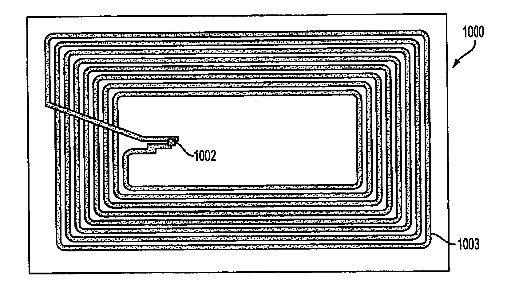
[0009]According to another embodiment of the invention, a security apparatus for indicating tampering is provided. Here, an object may be provided with a conducting path having at least two end points. A security label is arranged on the object. The security label may be a tamper indicating label as described above and should include RFID components and a destructible conducting path between the RF components and each individual end point.
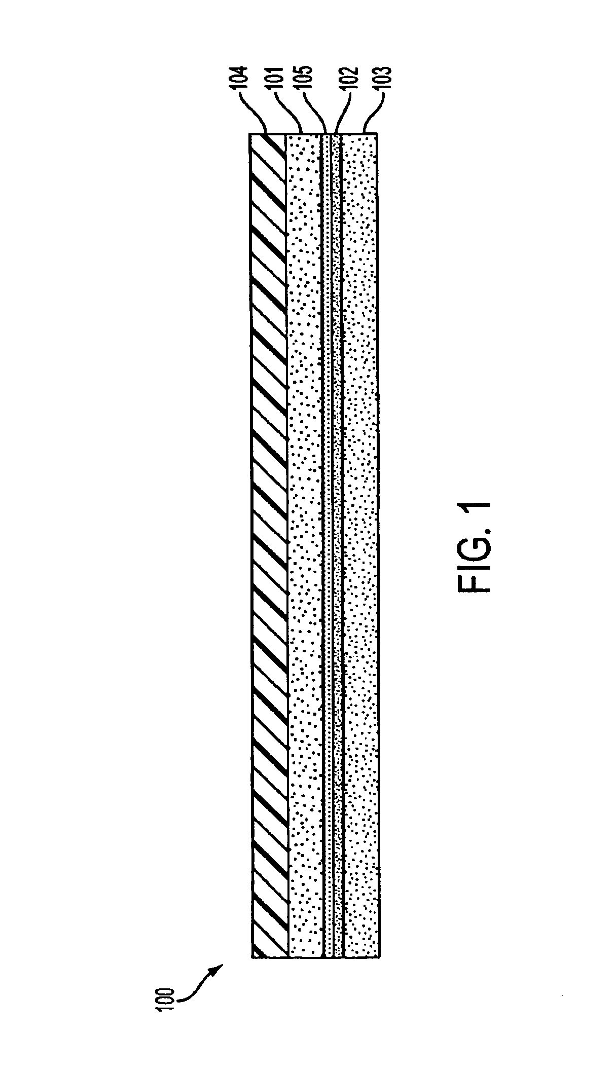
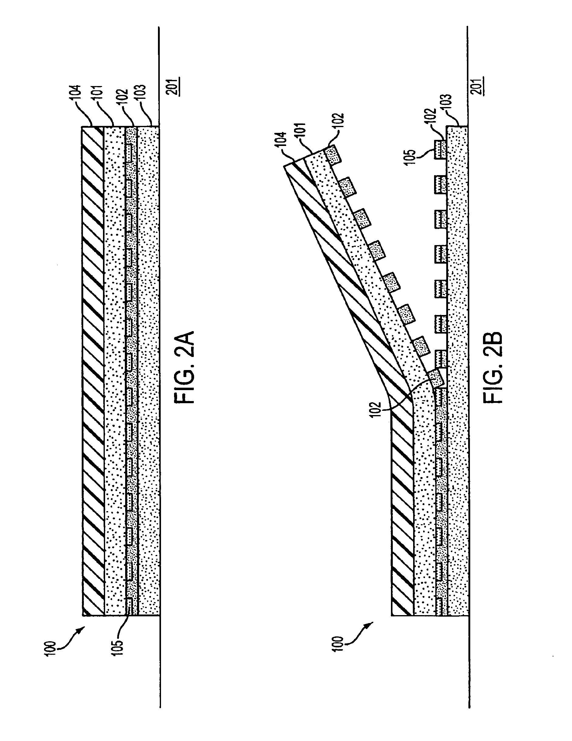
[0010]In one of the more detailed embodiments of the invention, a security label is combined with an object. The security label may comprise RFID components and means for attaching the RFID components to the object. Destructible electronics may be connected to the RFID components. The destructible electronics can be broken when the label is at least partially removed from the object. The object comprises a surface for receiving the security label and a conducting path having two ends. The ends of the conducting path may be connected to

Problems solved by technology

A disadvantage of current pressure sensitive RFID label technology is that it does not allow the remote determination of whether or not a label has been tampered with or removed and relocated.

Method used


Image

  • Tamper indicating radio frequency identification label
  • Tamper indicating radio frequency identification label
  • Tamper indicating radio frequency identification label

Examples


Embodiment Construction

[0028]The term “passive”, as used herein, refers to an RFID label or transponder which does not include an on-board power source such as a battery. The term “active”, as used herein, refers to an RFID label or transponder which includes an on-board power source such as a battery. The advantages of an active RFID label, relative to a passive RFID label, are that an active RFID label can include continuous on-board functions such as a clock, and can usually enable longer data reading and writing distances. A disadvantage of active RFID labels, relative to passive RFID labels, is that active RFID labels are physically larger due to the need to carry an on-board power source.

[0029]It should be appreciated that the terms label and tag may be used interchangeably in this document. Where the term label is used, the term tag may validly be substituted. The essential difference between the two are the thicknesses and types of material used in the construction. In general a label will be made...


PUM


Abstract

A tamper indicating label is provided. The label may include RFID components and a tamper track coupled to the RFID components. The tamper track should be constructed from a destructible conducting path. Additionally, the tamper track can be formed such that it is damaged when the label is tampered. In one embodiment, adhesion characteristics of the tamper track are adapted to break apart the tamper track when the label is tampered, for example, by removal from an object. The RFID components may retain their RF capability and detect when the tamper track has been damaged to indicate that the label has been tampered. Alternatively, the RFID capability of the RFID components may be disabled when the tamper track is damaged, indicating tampering.

Description

[0001]This application claims the benefit of Provisional application Ser. No. 60 / 190,936, filed Mar. 21, 2000.BACKGROUND OF THE INVENTION[0002]Radio Frequency Identification (RFID) is being used increasingly as a means to identify goods at a distance, without requiring physical contact or even line of sight access to the goods. RFID enables information about an item to be stored on an item, and in some implementations also allows this stored information to be modified at a distance. The most compact and cost effective means to provide this RFID capability is by means of a pressure sensitive (i.e. self adhesive) label incorporating an RFID capability.[0003]The ability to detect remotely whether a pressure sensitive label or seal applied to an item has been tampered with or removed is becoming increasingly important in order to detect theft, product substitution, tampering, warranty violation and other problems.[0004]A disadvantage of current pressure sensitive RFID label technology i...

Claims


Application Information

Patent Timeline
IPC IPC(8): G06K19/073
CPCG06K19/073H01L23/573G06K19/0739H01L2924/0002H01L2924/00
Inventor ATHERTON, PETER S.
Owner MAJKOKH CORP
Learn More