Air outlet device for a vehicle, especially for an airplane

a technology for air outlet devices and airplanes, which is applied in the direction of space heating and ventilation details, heating types, domestic heating details, etc., can solve the problems of flow noise, unfavorable air outlet devices, and a rather material-intensive and therefore heavy design of the above-mentioned known air outlet devices, and achieves the effect of reducing costs and facilitating us

Inactive Publication Date: 2005-05-03
GOODRICH HELLA AEROSPACE LIGHTING SYST
View PDF6 Cites 12 Cited by
  • Summary
  • Abstract
  • Description
  • Claims
  • Application Information

AI Technical Summary

Benefits of technology

[0011]To reduce the constructional weight, the air outlet device according to the present invention comprises a valve body, which is of a hollow configuration. The valve body is preferably formed in two parts, notably in such a manner that the valve body is closed on its end facing towards the air intake opening of the nozzle body and is open at the closing end facing towards the air outlet opening. Thus, a valve body of this type is of a dome-shaped hollow design which can be produced in a simple manner, e.g. by injection molding. The open closing end can be closed by a cover member forming the second part of the two-part configuration of the valve body. This cover member, which can be provided after the manner of a (closure) plug, can be of a different color from the valve body. This makes it possible to adapt the design of the valve body to the interior design of the passenger cabin of the vehicle (airplane).
[0019]Already above, in connection with the guiding engagement between the coupling member and the holding element, the advantage of the segmented inner thread of the holding element by the formation of circumferentially spaced partial segments has been pointed out. The segmented inner thread does not only save weight but also facilitates the production of the holding element as an injection-molded (plastic) member. Thus, the quality of the outer surface of the holding element is increased without the need for a mechanical finishing treatment such as e.g. polishing. By the segmented inner thread, excess accumulation of material on the inner side of the holding element are avoided, thus reducing the shrinkage of the injection-molded holding element. The improved surface quality of the holding element is of advantage with regard to the air-tight insertion of the holding element in a corresponding holding recess in the ceiling paneling. In this context, it is to be noted that the holding elements of known air outlet devices are spherical so that the placement of such a spherical holding element in the holding recess will result in a ball-bearing arrangement which allows for an individual adjustment of the nozzle body with a spatial angular range. For the air-tight accommodation of the spherical holding element in the holding recess, a uniformly round surface of the holding element is required, which—as explained above—is enhanced by the segmented configuration of the inner thread. According to another aspect of the inventive air outlet device, the nozzle body comprises an operating member to be manually turned for adjustment and extending to a position external of the holding element, and a sleeve member arranged within the holding element and connected to the operating member for common rotation therewith. The operating member and the sleeve member are arranged to grip around the edge of the accommodating opening of the holding element having the nozzle body arranged for rotation thereon. Since the nozzle body is formed in two parts (operating member and sleeve member), these two parts can be inserted into the holding element from opposite sides. Thus, particularly, the operating member can have an outer diameter larger than that of the accommodating opening because the operating member will not be inserted anymore into the accommodating opening via the central passage opening as provided in the air outlet device known from U.S. Pat. No. 5,399,119 but will be moved from outside against the holding element. In doing so, the operating member will remain external of the holding element so that its outer diameter can be selected to be larger than the diameter of the accommodating opening of the holding element.
[0022]The above-described two-part configuration of the nozzle body provides for a clear functional separation between the manipulation of the nozzle body and the guidance of the air stream through the nozzle body. The operating portion whereon the nozzle body is manually turned for setting the axial position of the valve body, is arranged to radially project beyond the accommodating opening of the holding element, thus covering the accommodating edge and consequently a possible annular gap generated between the nozzle body and the holding element. Due to its enlarged radial dimensions, the operating portion is manually gripped and operated (turned) in an easier manner.
[0023]As a result of its two-part configuration, the nozzle body—as already described above in connection with the closing end of the valve body—can be adapted to the design of the surface regions of the interior of the vehicle surrounding the air outlet device without the requirement that the whole valve body consist of a material of the same design that would thus possibly cause higher expenses.

Problems solved by technology

The above mentioned known air outlet device is of a rather material-intensive and thus heavy design.
Thus, the diameter of the operating member can be at best as large as the diameter of the accommodating opening while a still larger diameter is not possible.
Further, it is to be considered that the discharged air stream may cause flow noises when passing the nozzle body.

Method used


Image

  • Air outlet device for a vehicle, especially for an airplane
  • Air outlet device for a vehicle, especially for an airplane
  • Air outlet device for a vehicle, especially for an airplane

Examples


Embodiment Construction

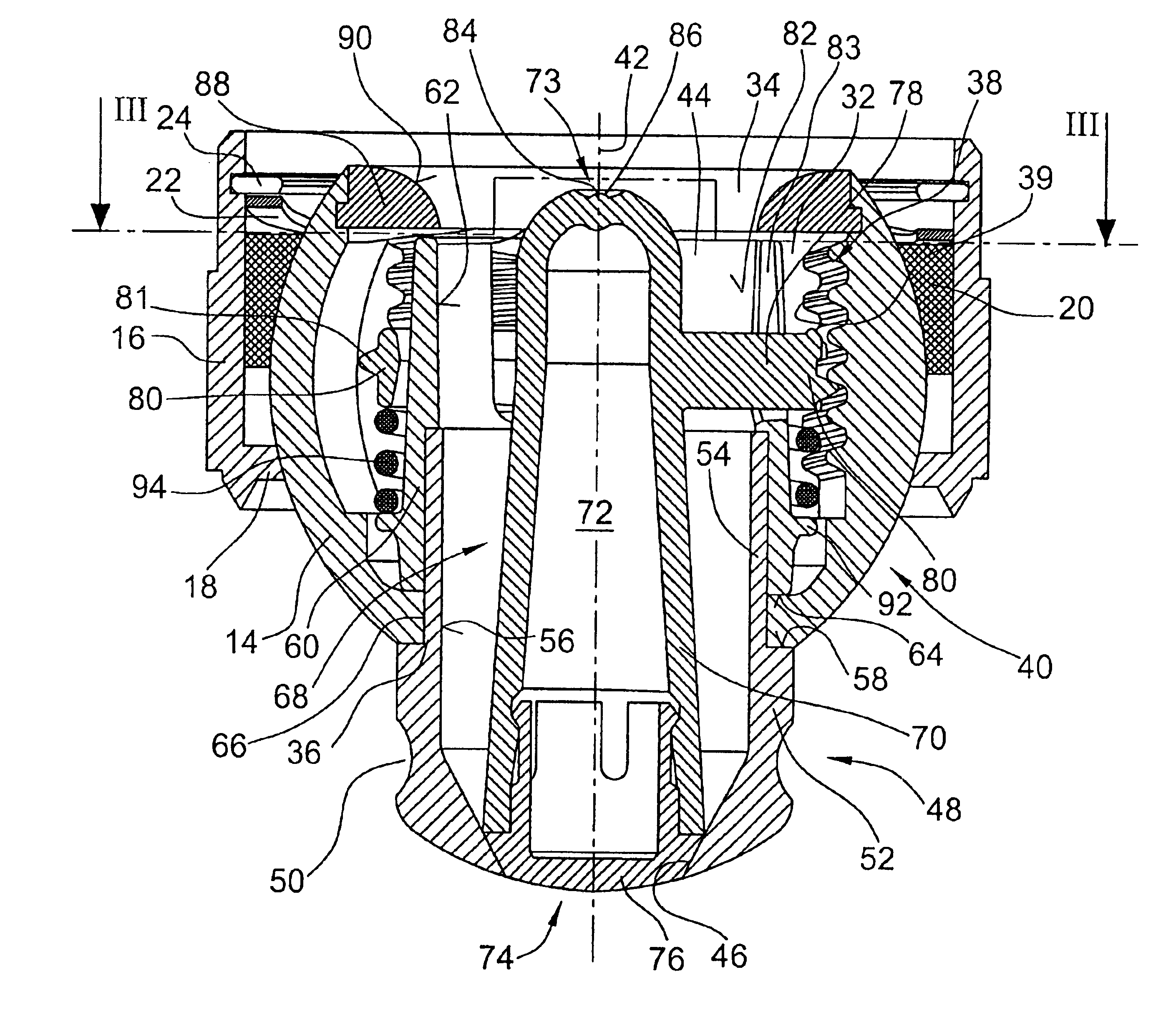
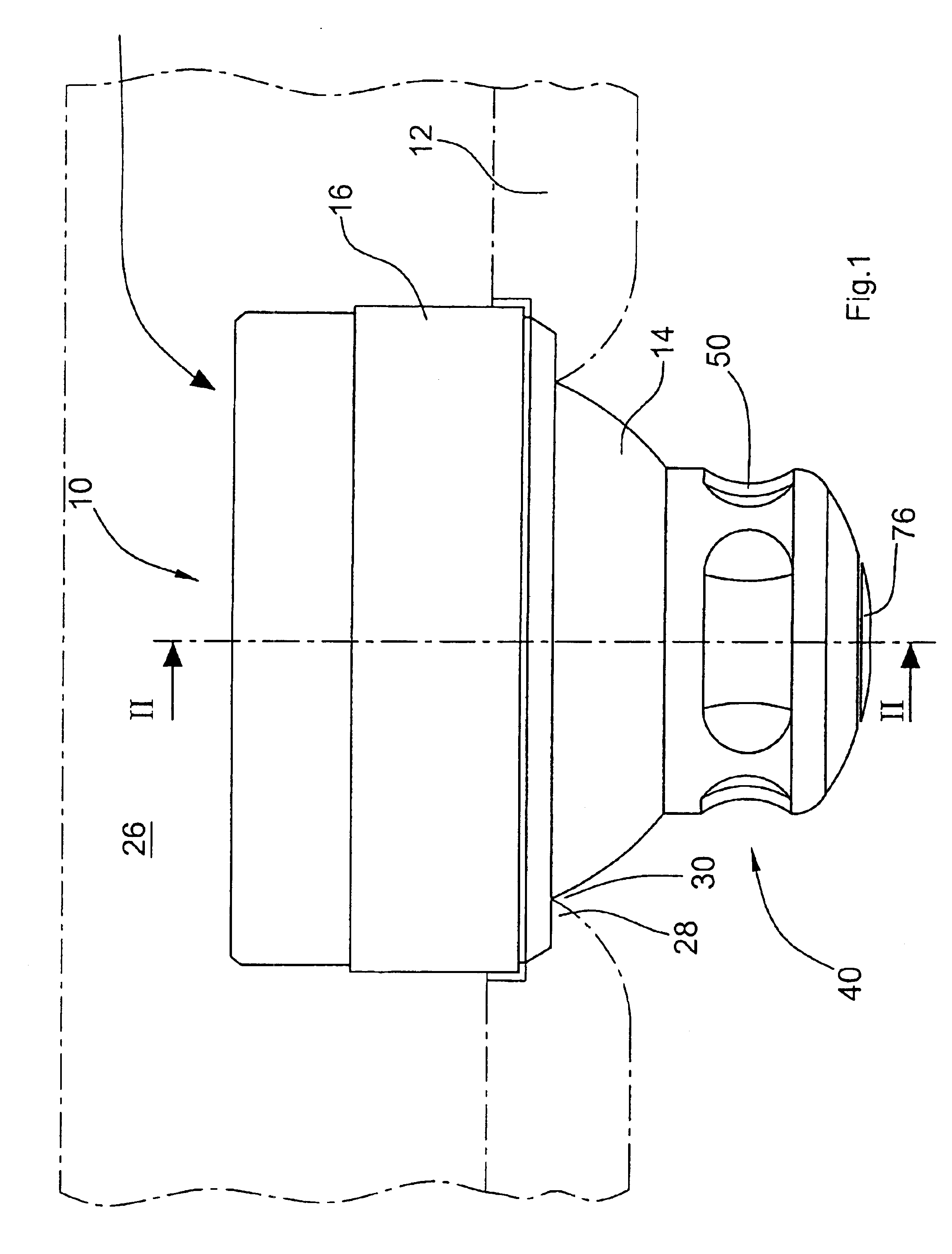
[0029]FIGS. 1 to 4 illustrate the configuration of an air outlet device 10 and the cooperation of the various components of the device 10. According to FIG. 1, the air outlet device 10 is arranged in the ceiling paneling 12 above a passenger seat e.g. of an airplane or bus. By manual operation of the air outlet device 10, the intensity and the direction of a discharged air flow can be changed.

[0030]The air outlet device 10 comprises a spherical holding element 14 arranged in a cylindrical accommodating element 16 to be pivoted in element 16 within a spatial angle dictated by the constructional design. This accommodating element 16 is shaped after the manner of a shell and on its end adjacent the ceiling paneling 12 is provided with an inner flange 18 (cf. FIG. 2) abutting the spherical outer side of spherical holding element 14. The spherical holding element 14 is inserted, from the end of accommodating element 16 opposite the inner flange 18, into a support element 20. The outer si...


PUM


Abstract

An air outlet device for a vehicle, especially for an aircraft, comprises a nozzle body with an air intake opening and an air outlet opening. The air outlet device further comprises a holding element formed with an accommodating opening having the nozzle body supported therein for rotation about a longitudinal axis extending through the air intake opening and the air outlet opening, and a valve body arranged coaxially within the nozzle body and guided by the holding element. Upon rotation of the nozzle body, the valve body can be displaced in the nozzle body between a closing position for blocking the air outlet opening and a maximum opening position for clearing the air outlet opening to the maximum extent. The valve body is of a hollow configuration.

Description

[0001]This non-provisional application, which is a divisional of co-pending application Ser. No. 10 / 042,152 filed on Jan. 11, 2002 U.S. Pat. No. 6,589,109, the entire contents of which are hereby incorporated by reference, and claims priority under 35 U.S.C. §119(a) on Patent Application No. 101 01 232.2, filed in Germany on Jan. 11, 2001, which is also herein incorporated by reference.BACKGROUND OF THE INVENTION[0002]The present invention relates to an air outlet device for a vehicle.[0003]As a common feature in vehicles, particularly in airplanes and busses, it is provided that each passenger can set a cooling air stream individually for his or her convenience by means of an air discharge nozzle arranged in the ceiling above the seat. Such air outlet devices (“air showers”) comprise a nozzle body to be selectively closed and set to different spatial configurations so that the discharged air stream can be oriented correspondingly.[0004]An air outlet device of the above type is know...

Claims


Application Information

Patent Timeline
IPC IPC(8): B60H1/34B64D13/00F24F13/065F24F13/06
CPCB60H1/3442B64D13/00F24F13/065Y02T50/44B64D2013/003Y02T50/40
Inventor THOMASSIN, STEFANPOEHLAU, FRANKKURZ, KLAUS
Owner GOODRICH HELLA AEROSPACE LIGHTING SYST
Why Eureka
Try Eureka