Gas stream vortex mixing system

a mixing system and gas stream technology, applied in the field of gas mixing, can solve the problems of difficult mixing of ammonia before the scr, difficult to achieve uniform constituent gas mixture, and dangerous combustion gases produced by power plants, etc., to achieve the effect of reducing gas flow resistance, generating lift, and strong vorticity

Inactive Publication Date: 2005-05-03
LUMINANT GENERATION CO LLC
View PDF27 Cites 10 Cited by
  • Summary
  • Abstract
  • Description
  • Claims
  • Application Information

AI Technical Summary

Benefits of technology

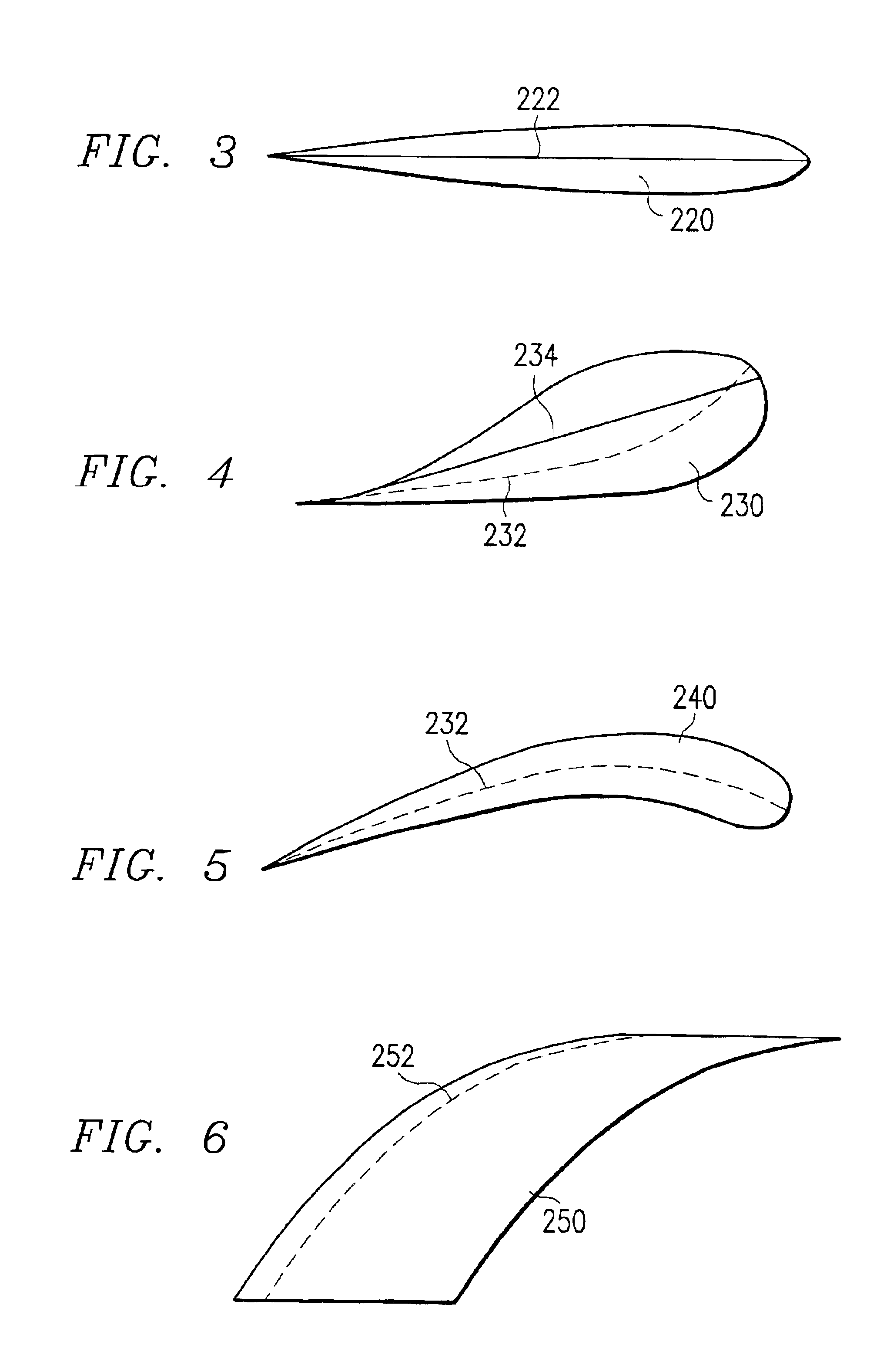
[0014]In another embodiment, the present invention provides a method of mixing gas by creating a predictable and ordered vorticity. The method includes providing a gas stream vortex mixing system having a duct provided with an outer surface defining an interior passageway operable for communicating a combustion gas. The gas stream vortex mixing system is further provided with at least one wing having an asymmetrical airfoil shape with a defined camber line such that the wing is operable to more efficiently generate lift, resulting in stronger vorticity at lower gas flow resistance.
[0015]In yet another embodiment, the present invention provides for a more simple way to achieve most of the positive effects by shaping the wing from a flat plate and forming the desired camber line into the plate along the span of the wing.

Problems solved by technology

Power plants produce dangerous combustion gases, such as NOx (oxides of nitrogen like NO and NO2), which are exhausted as a by-product of electric generation.
However, a uniform constituent gas mixture is difficult to achieve given the volume of combustion gas which must be uniformly mixed within the large ducts.
Frequently, the constituent gas flowing within the ducts develops small channels containing high concentrations of the various flue gas constituents (CO, CO2, NOx, for example) and the injected ammonia, or rope flows, while the constituent gas throughout the remaining duct cross section will contain low concentrations of NOx making proper mixing with ammonia prior to the SCR most difficult.
When such inhomogeneous constituent gas is passed through the catalyst, the rope flow zones exit the catalyst with high levels of flue gas constituents and / or ammonia that were not reacted by the catalyst due to the improper mixing of flue gas and ammonia.
While this does lower NOx, increasing the ammonia concentration is costly, inefficient, and results in increased ammonia emissions.
However, such obstacles create only turbulent flow of the combustion gases and provide only minimum improvement of the mixture of constituent gases.
Additionally, the turbulence inducers generate resistance in the ducts which reduces the efficiency of the flow of combustion gases through the ducts and increases the load on the fan systems that move the combustion gases through the ducts.

Method used


Image

  • Gas stream vortex mixing system
  • Gas stream vortex mixing system
  • Gas stream vortex mixing system

Examples


Embodiment Construction

[0031]It should be understood at the outset that although an exemplary implementation of the present invention is illustrated below, the present invention may be implemented using any number of techniques, whether currently known or in existence. The present invention should in no way be limited to the exemplary implementations, drawings, and techniques illustrated below, including the exemplary design and implementation illustrated and described herein.

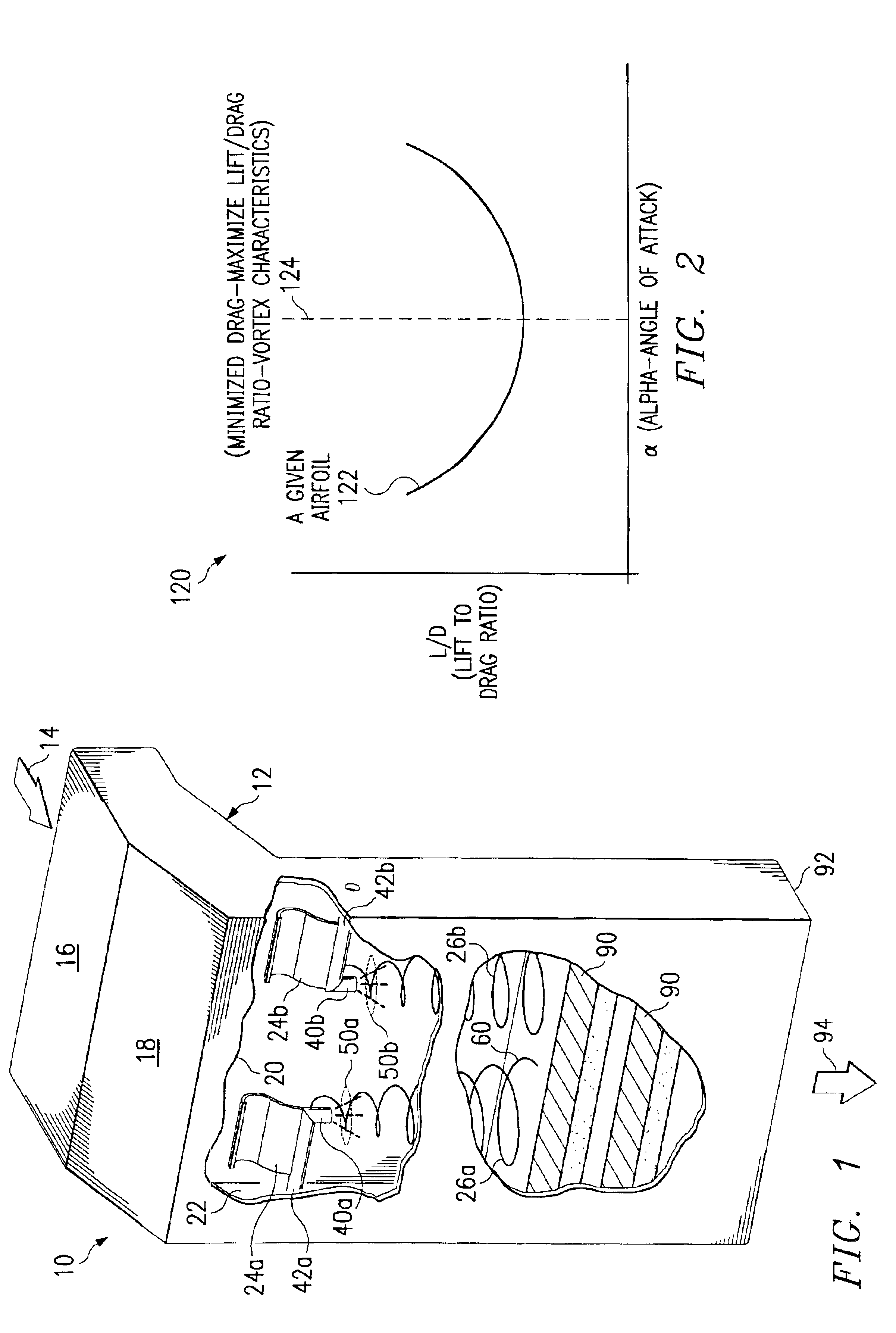
[0032]FIG. 1 is a side elevational view of a gas stream vortex mixing system 10 constructed in accordance with the present invention. The gas stream vortex mixing system 10 includes a duct 12, also commonly referred to as a flue, which is in communication with the combustion chamber of an electric power plant (not shown).

[0033]The duct 12 may be constructed from a variety materials, such as sheet metal, is sized to receive a combustion gas 14 from the power plant combustion chamber (not shown). The manufacture and use of ducts 12 to ...


PUM

PropertyMeasurementUnit
sizeaaaaaaaaaa
sizeaaaaaaaaaa
angle of attackaaaaaaaaaa

Abstract

A gas stream vortex mixing system for mixing gas is provided. The gas stream vortex mixing system includes a duct provided with an outer surface defining an interior passageway operable for communicating a gas. The gas stream vortex mixing system further includes at least one nozzle and at least one wing. The wing is disposed within the interior passageway of the duct and is operable for generating at least one vortex. The nozzle is disposed within the interior passageway of the duct. The nozzle is operable to discharge a mixture into the interior passageway of the duct.

Description

TECHNICAL FIELD OF THE INVENTION[0001]This invention relates in general to the field of gas mixing and more particularly, but not by way of limitation, to a gas stream vortex mixing system and method for mixing power plant combustion exhaust gas.BACKGROUND OF THE INVENTION[0002]The electric utility industry strives to efficiently provide electric power while minimizing the impact that electrical generation has on the environment. One specific point of concern is reducing harmful exhaust gas emissions from power plants.[0003]Power plants produce dangerous combustion gases, such as NOx (oxides of nitrogen like NO and NO2), which are exhausted as a by-product of electric generation. The combustion or flue gases are carried by large ducts or flues through treatment systems intended to reduce the NOx emissions. One commonly employed treatment process, called selective catalytic reduction (SRC), reduces NOx emissions by injecting an ammonia mixture into the combustion gases and passing th...

Claims


Application Information

Patent Timeline
Patent Type & Authority Patents(United States)
IPC IPC(8): B01F3/00B01F3/02B01F5/06F23D14/46F23D14/62B01F5/00B01F23/10
CPCB01F3/02B01F5/061F23D14/62F23D2900/14701B01F2005/0622B01F2005/0017B01F23/10B01F2025/913B01F25/43171B01F25/431B01F25/4315
Inventor PHILLIPS, BARRY L.
Owner LUMINANT GENERATION CO LLC
Why Eureka
Try Eureka