Micro-ring resonator

a resonator and micro-ring technology, applied in the direction of optical resonator shape and construction, instruments, etc., can solve the problems of increasing the overall length of the resonator, the loss of the resonator, and the loss of the material and surface roughness, and the current solution cannot provide a reduction of the resonator loss below a certain value, so as to achieve high coupling and low loss/rev

Inactive Publication Date: 2005-04-26
LAMBDA CROSSING
View PDF10 Cites 21 Cited by
  • Summary
  • Abstract
  • Description
  • Claims
  • Application Information

AI Technical Summary

Benefits of technology

[0012]It is a therefore a need in the art to design a resonator structure that provides for high coupling and low loss / rev.
[0014]The present invention solves the above problems by providing an improved resonator structure comprising a resonator waveguide having an optimized shape and geometry, which permits high coupling efficiency and significantly smaller loss / rev, as compared to the known resonators of the kind specified. The resonator structure according to the invention comprises a closed loop resonator for coupling to at least one waveguide that serves as a light input or output with respect to the resonator waveguide, wherein the resonator waveguide has a varying width across the circumferential region of the resonator. Generally, the closed loop can be of any shape having arc segments connected to each other either directly or through substantially straight segments of the resonator waveguide. Substantially circular resonators are preferred due to their smaller losses, and oval-like resonators are even more preferable since they provide an increased coupling as compared to a perfect circular ring resonator. The term “oval-like resonator” used herein signifies a resonator having a continuous closed loop shape formed by substantially arcuate end segments connected to each other either directly, or via substantially straight side segments extending therebetween (racetrack resonator).
[0015]The inventors have found that by providing a region of the closed loop resonator waveguide with varying width across the circumference decreases significantly the radiation losses of the resonator. By making this closed loop resonator with an oval-like shape, any required coupling to the waveguide can be provided without imposing difficult fabrication constraints and gap spacing. It should be understood that the width-varying region can be within the arc segment of the resonator, and can be achieved by making this region with a varying curvature, and / or the width-varying region can be within a substantially straight segment of the resonator waveguide. The closed loop resonator waveguide of the present invention can be used in a variety of applications such as optical filters, lasers, modulators, spectrum analyzers, wavelockers, interleave filters, optical add drop multiplexers and other applications.

Problems solved by technology

This, however, would result in a very small FSR, and also would increase the overall length of the resonator and losses related to the material and surface roughness.
Hence, the current solutions cannot provide a reduction in the resonator loss below a certain value.

Method used


Image

  • Micro-ring resonator
  • Micro-ring resonator
  • Micro-ring resonator

Examples


Embodiment Construction

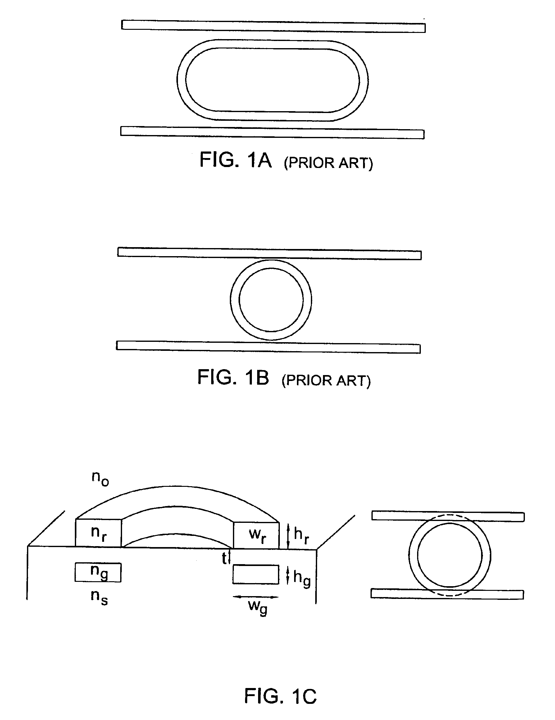
[0038]FIGS. 1A-1C illustrate the prior art ring resonator based structure. FIGS. 1A and 1B show structures utilizing, respectively, a race-track ring resonator and a circular resonator (perfect ring), both fabricated according to the single-layer approach, and FIG., 1C shows a structure utilizing circular resonator and the multi-layer approach [“Vertically coupled glass microring resonator channel dropping filters”, B. E. Little et al., IEEE Photonics Technology Letters vol. 11 no. 2, February 1999, p. 215-217].

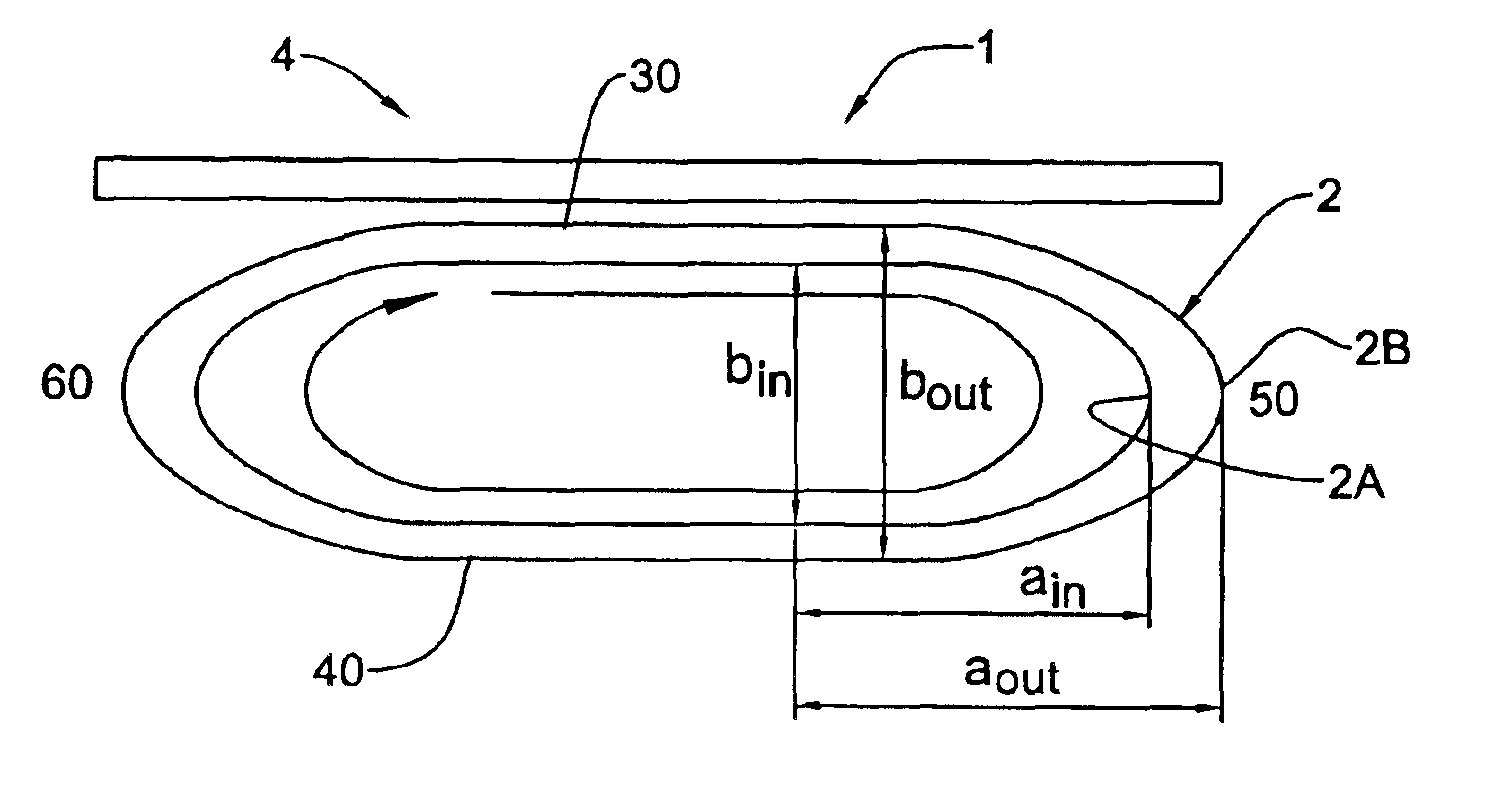
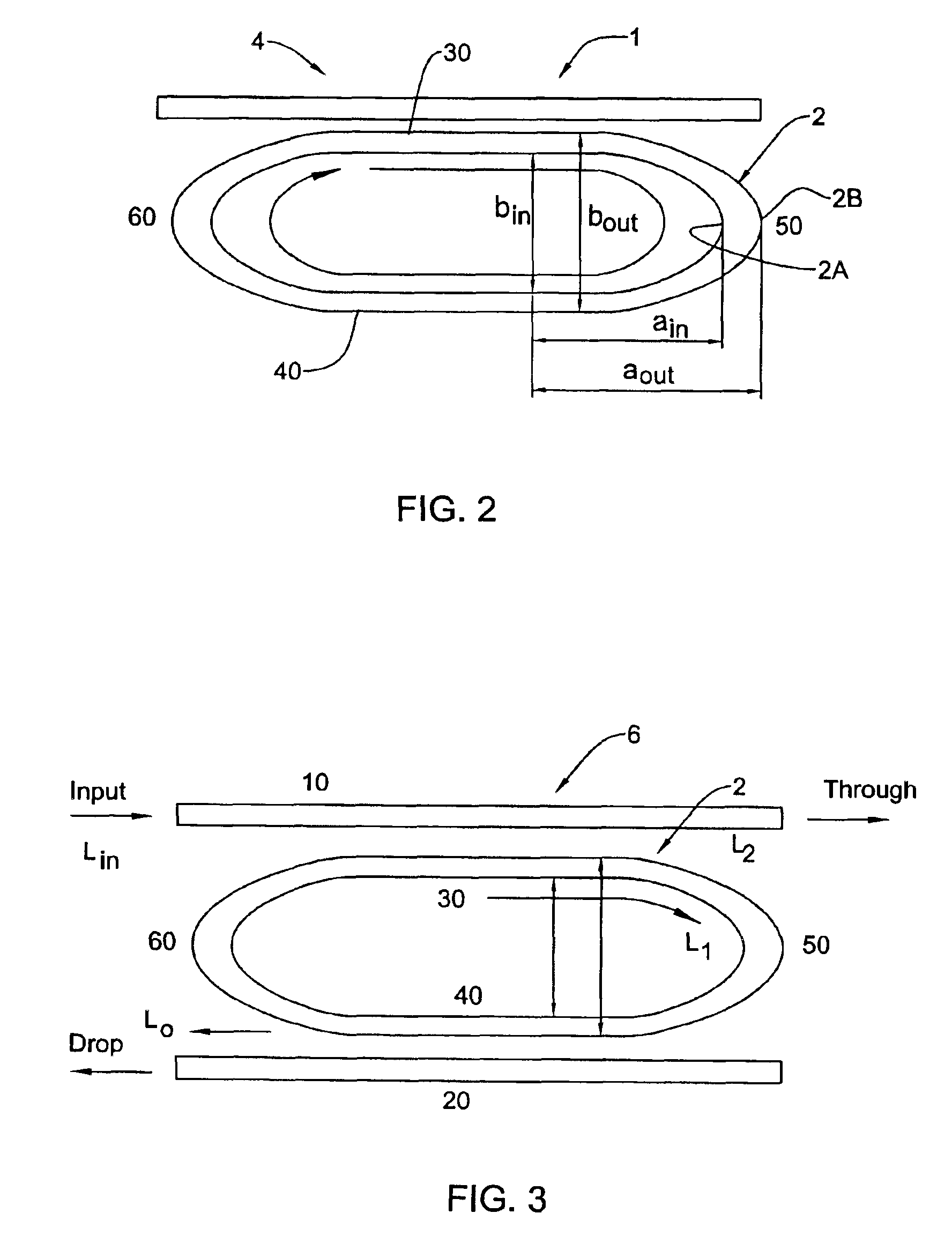
[0039]Referring to FIG. 2, there is illustrated a novel resonator structure 1 according to the invention. The structure 1 comprises a closed loop, preferably oval, resonator waveguide 2, and a waveguide 4, which provides the input and output to the resonator. Structure 1 can thus operate as the all pass filter device. In the present example, the waveguide 4 is substantially straight (linear waveguide), but it should be understood that it may be a closed loop resonator wavegui...


PUM


Abstract

A resonator structure is presented comprising a closed loop resonator waveguide having a width varying over the circumferential region of the resonator waveguide. The resonator structure can be used in various applications, such as optical filters, lasers, modulators, spectrum analyzers, wavelockers, interleave filters, and optical add drop multiplexers.

Description

FIELD OF THE INVENTION[0001]This invention relates to resonant optical cavities and more particularly to ring-like cavities used in integrated optical devices.BACKGROUND OF THE INVENTION[0002]An optical resonator is an important element, which can be incorporated into many of the components used for optical communication systems such as lasers, filters, routers, switches, etc. Such resonator can be easily realized in integrated optical devices with linear waveguides to form a Planar Lightwave Circuit (PLC). One of the most common roles of the optical resonator is to serve as a wavelength dependent coupler between two (or more) waveguides (input / output (I / O) waveguides). This is schematically illustrated in FIGS. 1A and 1B, wherein an oval-like or circular resonator serves for coupling between two linear waveguides. The light couples from one (input) linear waveguide into the resonator waveguide and from the resonator to the other (output) linear waveguide. In specific wavelengths, k...

Claims


Application Information

Patent Timeline
Patent Type & Authority Patents(United States)
IPC IPC(8): G02B6/12G02B6/34
CPCG02B6/12007G02B6/29343
Inventor SCHEUER, JACOBYADIN, YOAVMARGALIT, MOTI
Owner LAMBDA CROSSING
Why Eureka
Try Eureka