
Temperature-compensated electro-optical voltage sensor

Active Publication Date: 2005-04-26
HITACHI ENERGY SWITZERLAND AG
View PDF12 Cites 2 Cited by
  • Summary
  • Abstract
  • Description
  • Claims
  • Application Information

AI Technical Summary

Benefits of technology

[0022]By virtue of the silicone sheathing, it is possible to produce a sensor having very small dimensions and a low weight which nevertheless has a sufficient electrical insulation. Expensive, large, heavy insulation tubes, typically made of glass-fiber-reinfo

Problems solved by technology

Such a voltage sensor has the disadvantage that various approximation assumptions have to be made for the computational temperature compensation, and that the measured temperature does not nece

Method used


Image

  • Temperature-compensated electro-optical voltage sensor
  • Temperature-compensated electro-optical voltage sensor
  • Temperature-compensated electro-optical voltage sensor

Examples


Example

[0035]The reference symbols used in the drawings and their meaning are summarized in the List of designations. In principle, identical or at least identically acting parts are provided with the same reference symbols in the figures. The exemplary embodiments described represent the subject matter of the invention by way of example and have no restrictive effect.

WAYS OF EMBODYING THE INVENTION

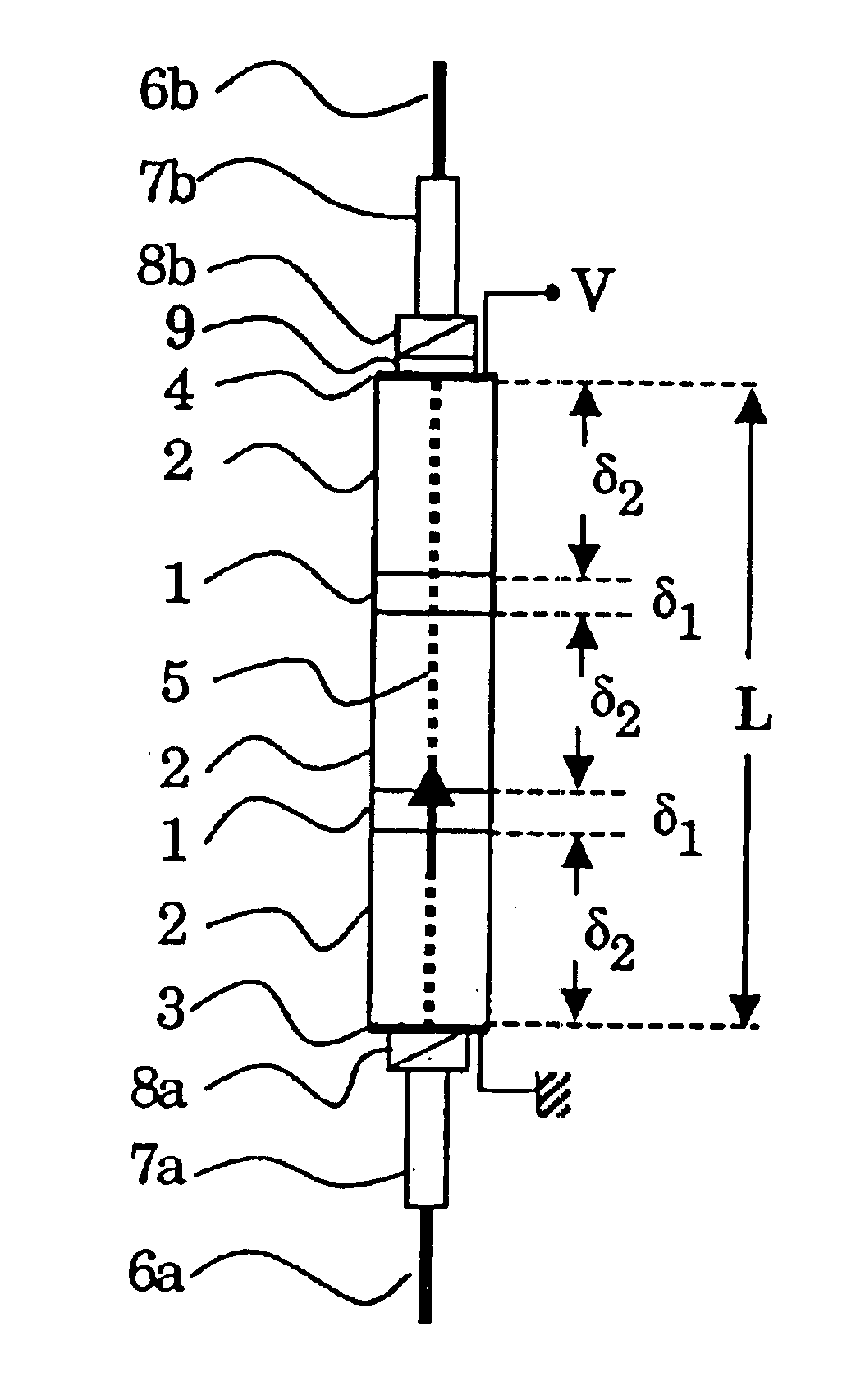
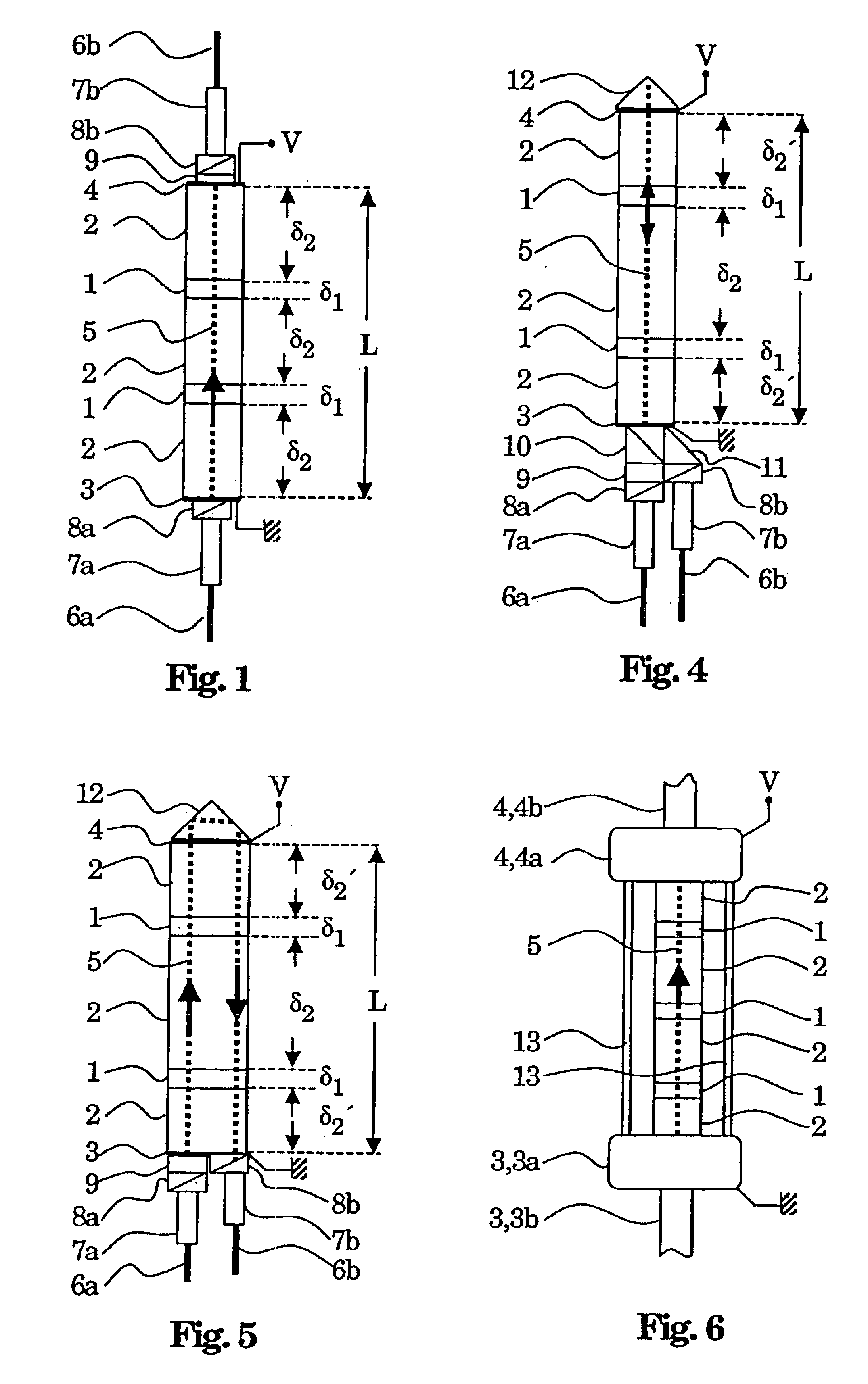
[0036]FIG. 1 shows a sensor in transmission geometry, comprising N=2 BGO crystal sheets 1 and N+1=3 sheets of fused silica. This stack of BGO and fused silica sheets forms a rod, a sensor rod. FIG. 1 illustrates principally the optical components. The BGO sheets 1 have a thickness δ1 and are arranged between the fused silica sheets 2 having the thickness δ2. In an advantageous manner, all the sheets are cylindrical with the same diameter. In an advantageous manner, all the BGO sheets have the same crystalline orientation. A respective electrode 3, 4 is preferably fitted to each end of the stack ...


PUM


Abstract

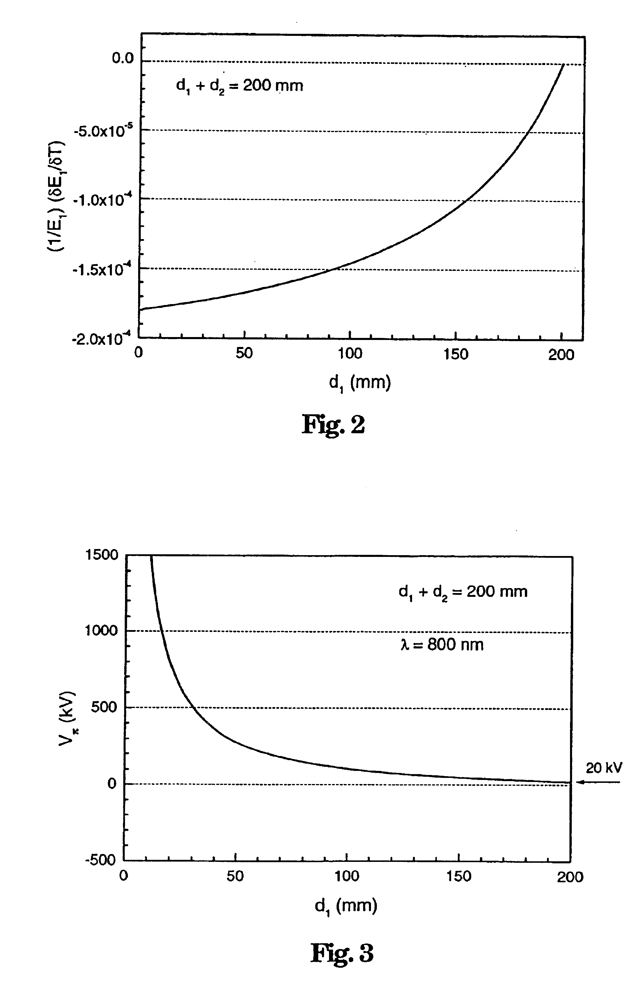
The electra-optical voltage sensor has an electra-optically active medium and a distance medium between two electrodes, between which the voltage V to be measured is present. The media and the thicknesses d1, d2 of the media are chosen in such a way that the measured voltage signal has no temperature dependence. By way of example, the thicknesses d1, d2 are chosen in such a way that the influence of the temperature dependences of critical electra-optical coefficients and dielectric constants of the media on the voltage signal cancel one another out. The two media are advantageously arranged in the form of a rod, comprising an alternating arrangement of cylindrical elements of the two media, between the electrodes. BGO and fused silica may advantageously be used as media. The sensor is preferably cast in silicone. It is possible to realize a mechanically stable, temperature-stabilized voltage sensor with low reflection losses, a large half wave voltage and a small sensitivity toward disturbances of the electric field.

Description

TECHNICAL FIELD[0001]The invention relates to the field of electro-optical voltage sensor technology, in particular of high-voltage measurement. It relates to an electro-optical voltage sensor in accordance with the preamble of patent claim 1 and to a method for electro-optical voltage measurement in accordance with the preamble of patent claim 15.PRIOR ART[0002]Such a voltage sensor and a corresponding method are disclosed for example in EP 0 682 261 A2. An electrical voltage V to be measured is applied to two ends of an electro-optical crystal. Linearly polarized light is radiated into the crystal and propagates therein in the form of two mutually orthogonally polarized light waves. The light is detected after traversing the crystal. As a result of the Pockels effect, a voltage-dependent birefringence is induced in the crystal, so that a change in polarization of the light that has emerged from the crystal, said change being proportional to the electrical voltage V to be measured,...

Claims


Application Information

Patent Timeline
IPC IPC(8): G01R15/24
CPCG01R15/242
Inventor BOHNERT, KLAUSFRANK, ANDREASBRANDLE, HUBERT
Owner HITACHI ENERGY SWITZERLAND AG
Learn More