Enhancements to high efficiency ceiling fan

a ceiling fan and high efficiency technology, applied in the direction of wind motor components, non-positive displacement fluid engines, liquid fuel engine components, etc., can solve the problems of excessive noise, flat ceiling fan blades, poor performance at high speeds, etc., and achieve the effect of reducing electrical power consumption and being more energy efficien

Inactive Publication Date: 2005-04-26
UNIV OF CENT FLORIDA RES FOUND INC
View PDF38 Cites 126 Cited by
  • Summary
  • Abstract
  • Description
  • Claims
  • Application Information

AI Technical Summary

Benefits of technology

[0013]The second objective of the subject invention is to provide ceiling fan blades that are more quiet and provide greater comfort than traditional flat planar ceiling fan blades.
[0015]The fourth objective of the subject invention is to provide ceiling fan blades that reduce electrical power consumption and are more energy efficient over traditional flat planar ceiling fan blades.
[0019]The eighth objective of the subject invention is to provide ceiling fan blades having reduced low operational forward speeds of less than approximately 75 revolutions per minute.

Problems solved by technology

These patents while moving air are not concerned with maximizing optimum downward airflow.
Furthermore, many of the flat ceiling fan blades have problems such as poor performance at high speeds, wobbling, and excessive noise that is noticeable to persons in the vicinity of the fan blades.
None of these propellers are designed for optimum airflow at low speeds of less than approximately 200 rpm which is the desired speeds used in overhead ceiling fan systems.
Using two pieces for each blade adds extreme costs in both the manufacturing and assembly of the ceiling itself.
Furthermore, the grooved connection point in the Volk devices would appear to be susceptible to separating and causing a hazard to anyone or any property beneath the ceiling fan itself.
Such an added device also has necessarily less than optimal aerodynamic properties.
Clearly, such a blades would not be aesthetically pleasing to the user to have various holes and ribs visible on the blades, and there is no description for increasing airflow with such an arrangement.
U.S. Pat. No. 5,860,788 to Sorensen mentions some old uses of having four to six blade fans that cover approximately 5 feet(60 inches) but has not no data on low speed operation, nor on using three blades, nor on using any twisted blade configurations, and would not have enhanced efficiency over conventional ceiling fan operation.
Although larger ceiling fans with diameters greater than 54 inches have been produced, these fans have not incorporated enhancements to the fan blade, such as maximizing twist, taper and air foil configurations to optimize air moving performance.

Method used


Image

  • Enhancements to high efficiency ceiling fan
  • Enhancements to high efficiency ceiling fan
  • Enhancements to high efficiency ceiling fan

Examples


Embodiment Construction

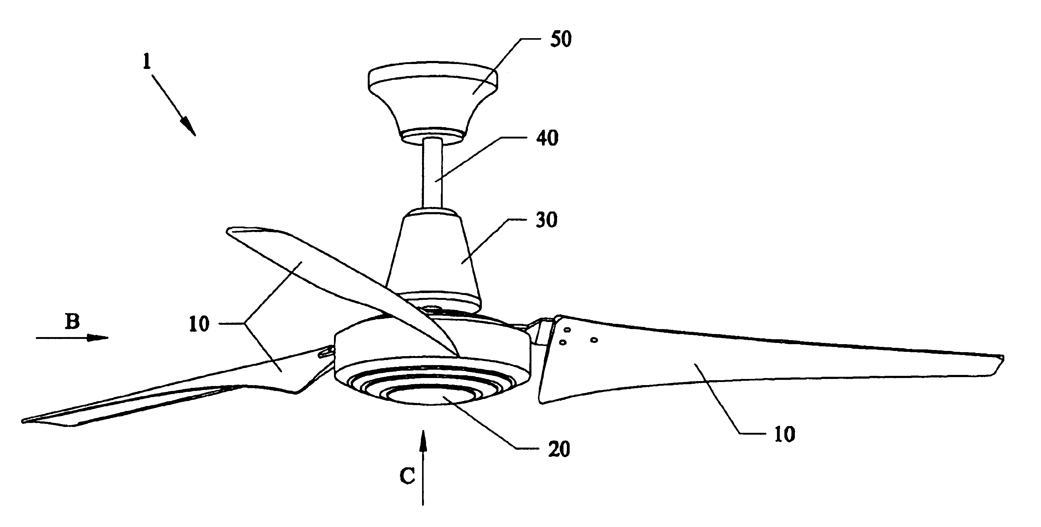
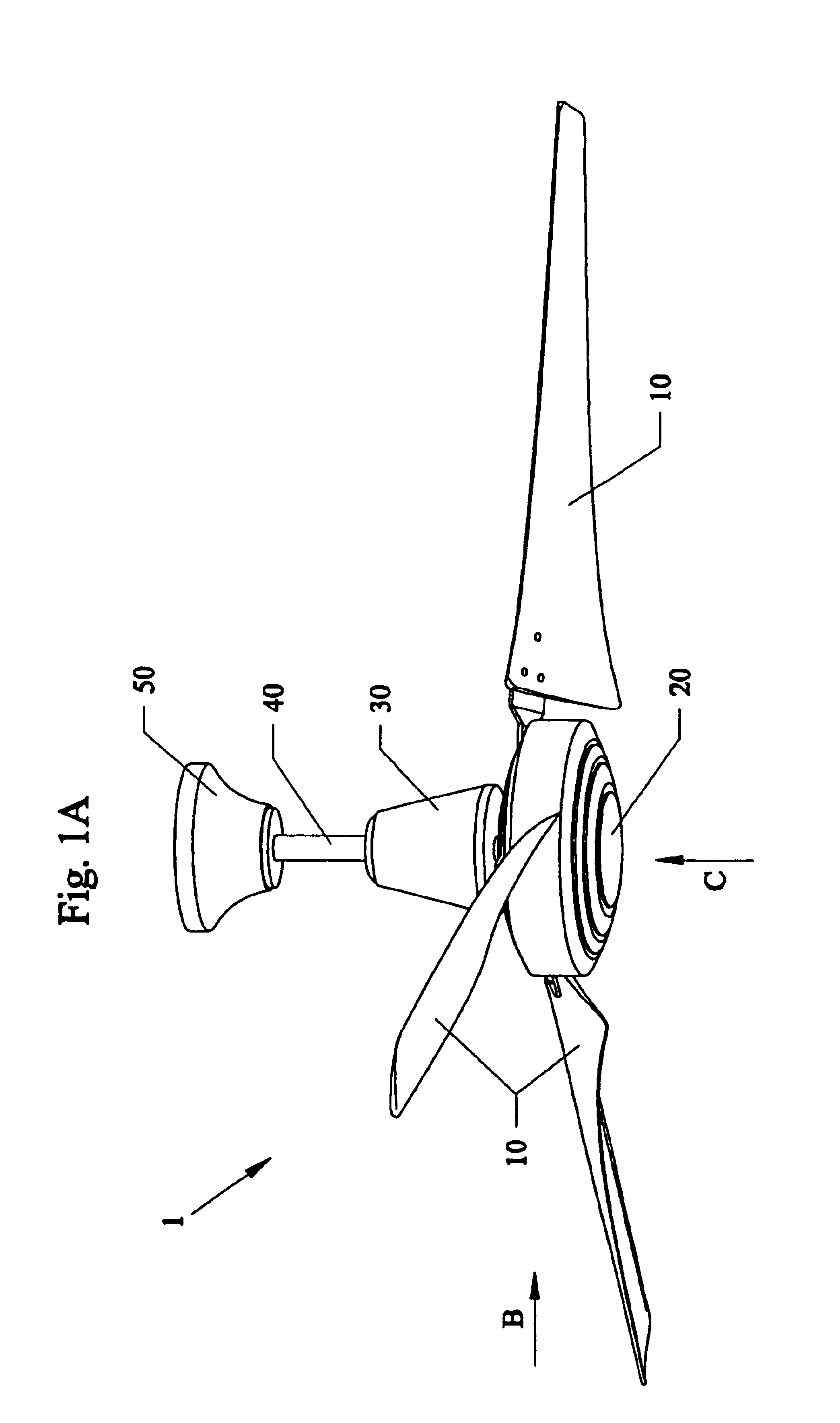
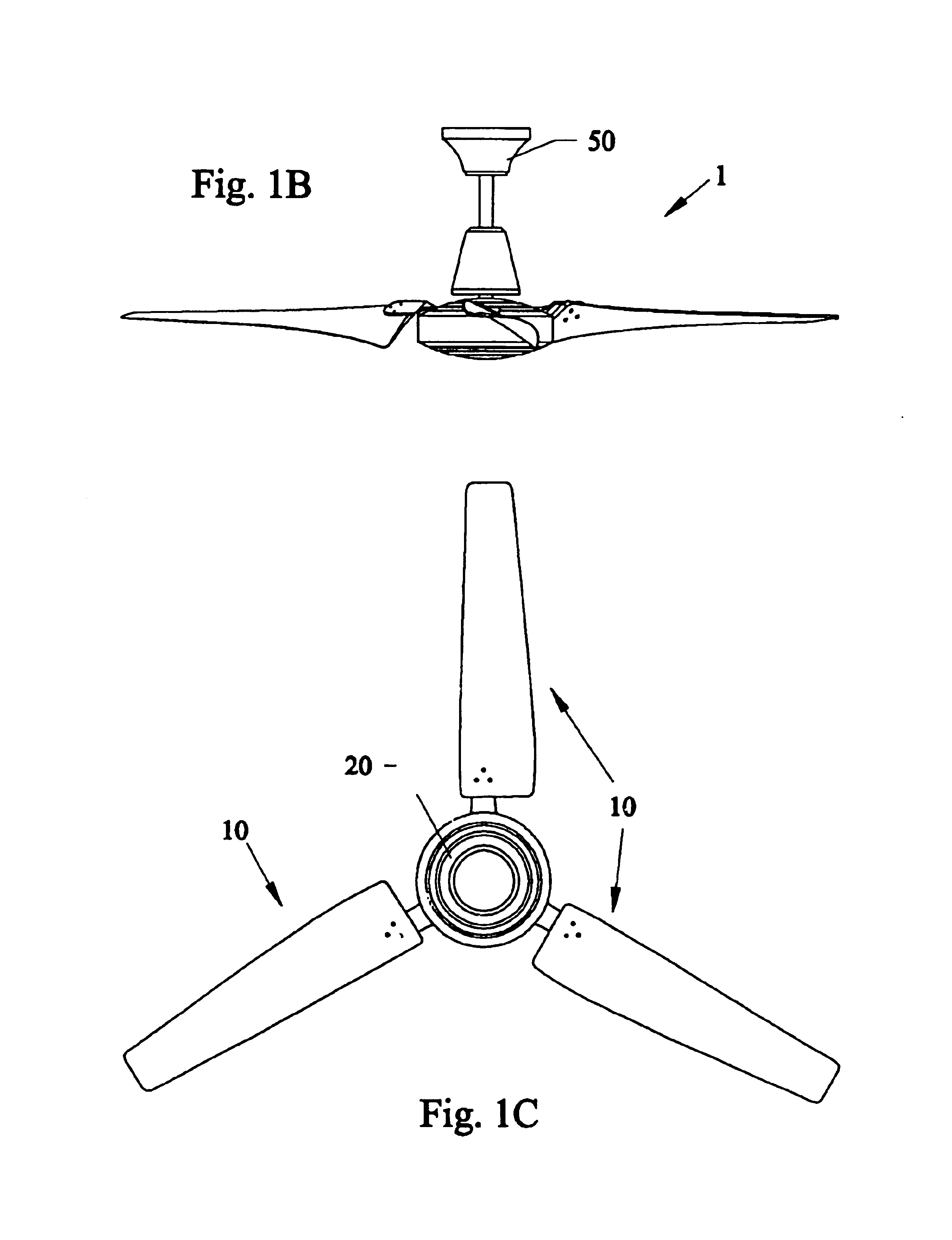
[0041]Before explaining the disclosed embodiments of the present invention in detail it is to be understood that the invention is not limited in its application to the details of the particular arrangement shown since the invention is capable of other embodiments. Also, the terminology used herein is for the purpose of description and not of limitation.

[0042]Testing of novel ceiling fan blades were first described in detail to parent patent application to the subject invention, namely U.S. patent Ser. No. 09 / 056,428 filed Apr. 7, 1998, now U.S. Pat. No. 6,039,541, and incorporated by reference. The initial novel blades were tested between May and June, 1997 at the Florida Solar Energy Center® in Cocoa, Fla., and included three parameters of measurement data: airflow(meters per second(m / s), power(in watts) and speed(revolutions per minute(rpm)). Those novel ceiling fan blades far surpassed the operating parameters of various ceiling fans in operation, as do the subject fan blades of ...


PUM


Abstract

Twisted ceiling fan blades for low, medium and high speed operation of less than approximately 250 rpm. The novel blades twisted blades can be configured for 60″ and 64″ diameter fans, and have less blades (3 for example) than conventional flat type bladed fans having 4, 5 blades and have greater air flow and less power draw results than the conventional flat 54 inch fans. Any of the novel twisted blades of 54″, 60″ and 64″ can be run at reduced speeds, drawing less Watts than conventional fans and still perform better with more air flow and less problems than conventional flat type conventional blades.

Description

[0001]This invention relates to ceiling fans, and in particular to three or more blade ceiling fans having large diameters of approximately 60 to approximately 64 inches, along with operating fan blades at reduced rotational speeds (approximately 75 to approximately 250 rpm) for reduced energy consumption with larger air movement volumes, and the invention claims the benefit of priority to Provisional Application 60 / 342,564 filed Dec. 26, 2001, and this invention is a Continuation-In-Part of U.S. application Ser. No. 09 / 976,515 filed Oct. 12, 2001, which claims the benefit of Provisional Application 60 / 265,241 filed Jan. 31, 2001, and this invention is a continuation-in-part of U.S. Ser. No. 09 / 711,599 filed Nov. 13, 2000 now U.S. Pat. No. 6,415,984, which is a divisional application of U.S. Ser. No. 09 / 415,883 filed Oct. 8, 1999 now U.S. Pat. No. 6,189,799, which is a divisional application of U.S. Ser. No. 09 / 067,236 filed Apr. 27, 1998 now U.S. Pat. No. 5,996,898 which is incorpo...

Claims


Application Information

Patent Timeline
IPC IPC(8): F04D25/08F04D27/00F04D25/02F24F11/00F24F7/007G05D23/19
CPCF04D25/088F04D27/00F24F7/007F24F11/0034F24F11/0012Y10S416/05F24F11/0079F24F2011/0036Y02B30/746F24F11/30F24F2110/10F24F2120/10F24F2120/14F24F11/77Y02B30/70F24F11/46
Inventor PARKER, DANNY S.SU, GUAN HUAHIBBS, BART D.
Owner UNIV OF CENT FLORIDA RES FOUND INC
Why Eureka
Try Eureka