
Rotating stream sprinkler with ball drive

a technology of rotating stream and sprinkler, which is applied in the direction of spraying nozzles, movable spraying apparatus, spraying apparatus, etc., can solve the problems of rapid sprinkler wear and distorted water stream delivery patterns, and significantly reduce the rotational speed of the vaned deflector during sprinkler operation. , to achieve the effect of improving the overall complexity and cost of irrigation sprinkler, and avoiding the effect of affecting the operation

Inactive Publication Date: 2005-04-26
RAIN BIRD CORP
View PDF15 Cites 61 Cited by
  • Summary
  • Abstract
  • Description
  • Claims
  • Application Information

AI Technical Summary

Benefits of technology

The invention is a rotating stream sprinkler that uses a vaned deflector to sweep small water streams over a surrounding terrain area to irrigate vegetation. The sprinkler includes a turbine driven ball drive rotor with drive balls that impact engage with anvils on the deflector to rotate it. A speed control brake is used to maintain the deflector's rotation speed constant within a range of normal water supply pressures and flow rates. The invention provides a reliable and efficient irrigation system that can adjust to varying water supply conditions.

Problems solved by technology

In this regard, in the absence of speed control or brake means, the vaned deflector can be rotatably driven at an excessive speed up to and exceeding 1,000 rpm, resulting in rapid sprinkler wear and distorted water stream delivery patterns.
In such designs, the viscous fluid applies a substantial drag to rotor element rotation which significantly reduces the rotational speed of the vaned deflector during sprinkler operation.
Unfortunately, these parameters can vary during any given period or cycle of sprinkler operation, resulting in corresponding variations in the water stream delivery patterns for irrigating the surrounding vegetation.
In addition, such fluid brake concepts require the use and effective sealed containment of a viscous fluid such as a silicon-based oil or the like, which undesirably increases the overall complexity and cost of the irrigation sprinkler.
Such continuous rotation of the deflector inherently reduces the range of throw of the outwardly projected water streams.

Method used


Image

  • Rotating stream sprinkler with ball drive
  • Rotating stream sprinkler with ball drive
  • Rotating stream sprinkler with ball drive

Examples


Embodiment Construction

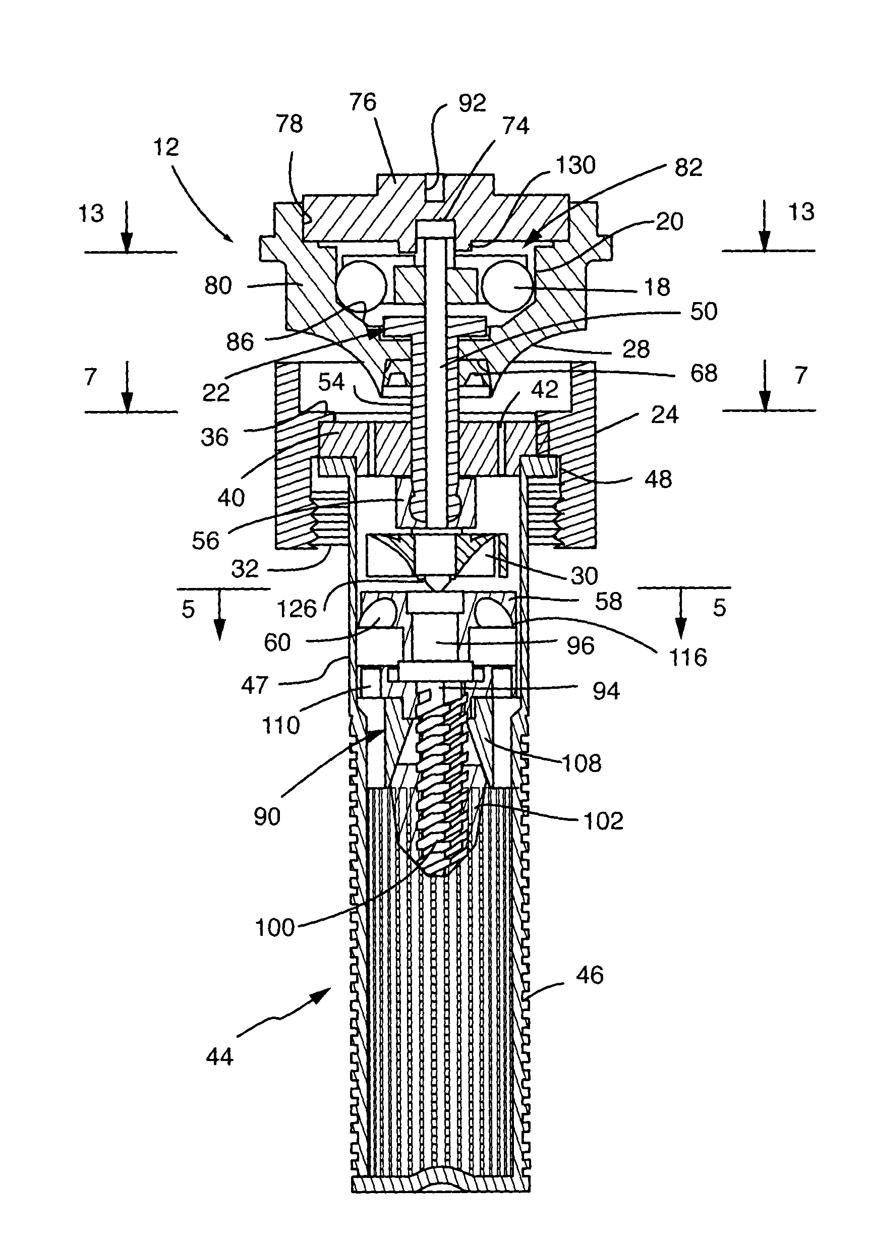
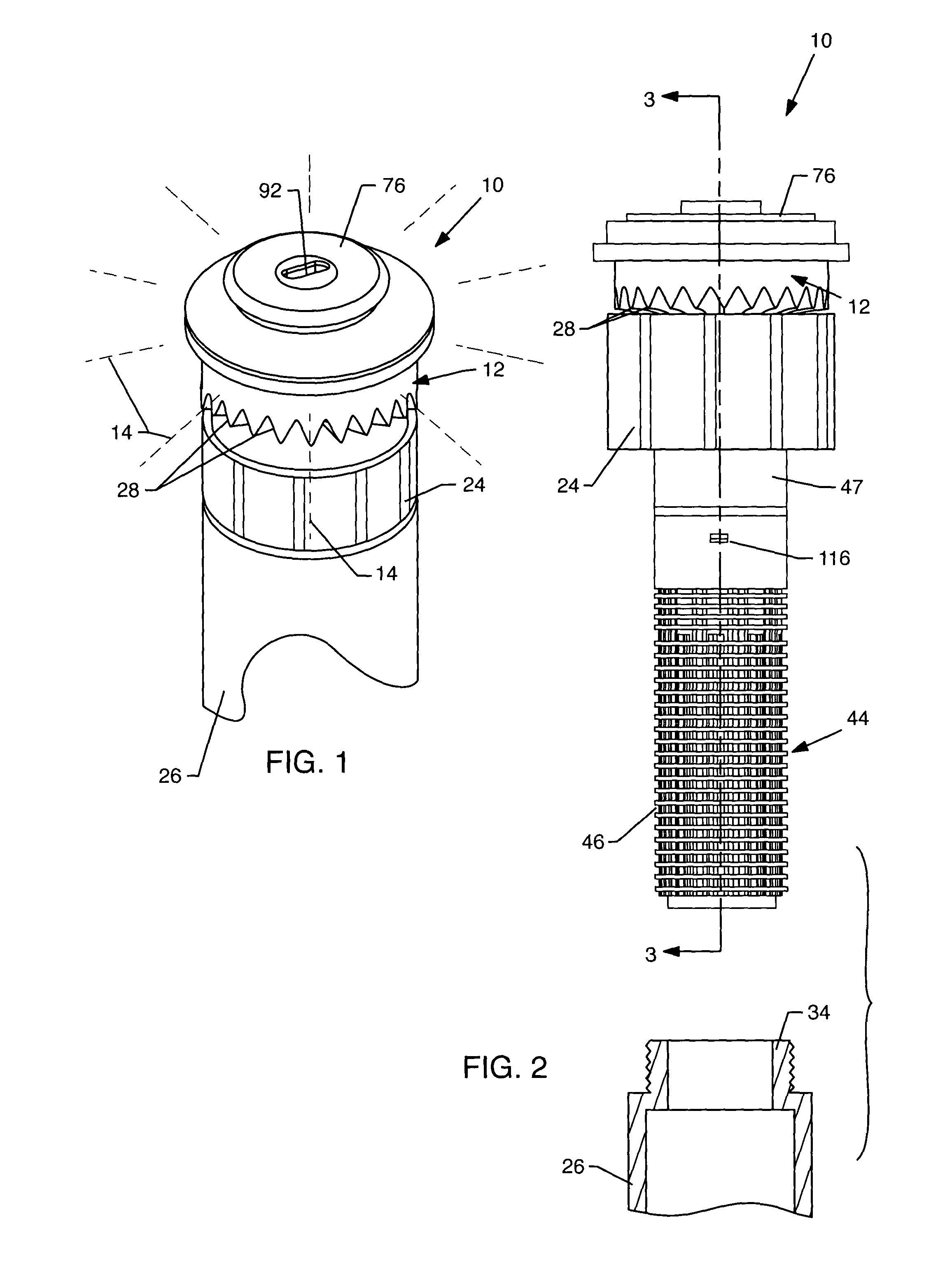
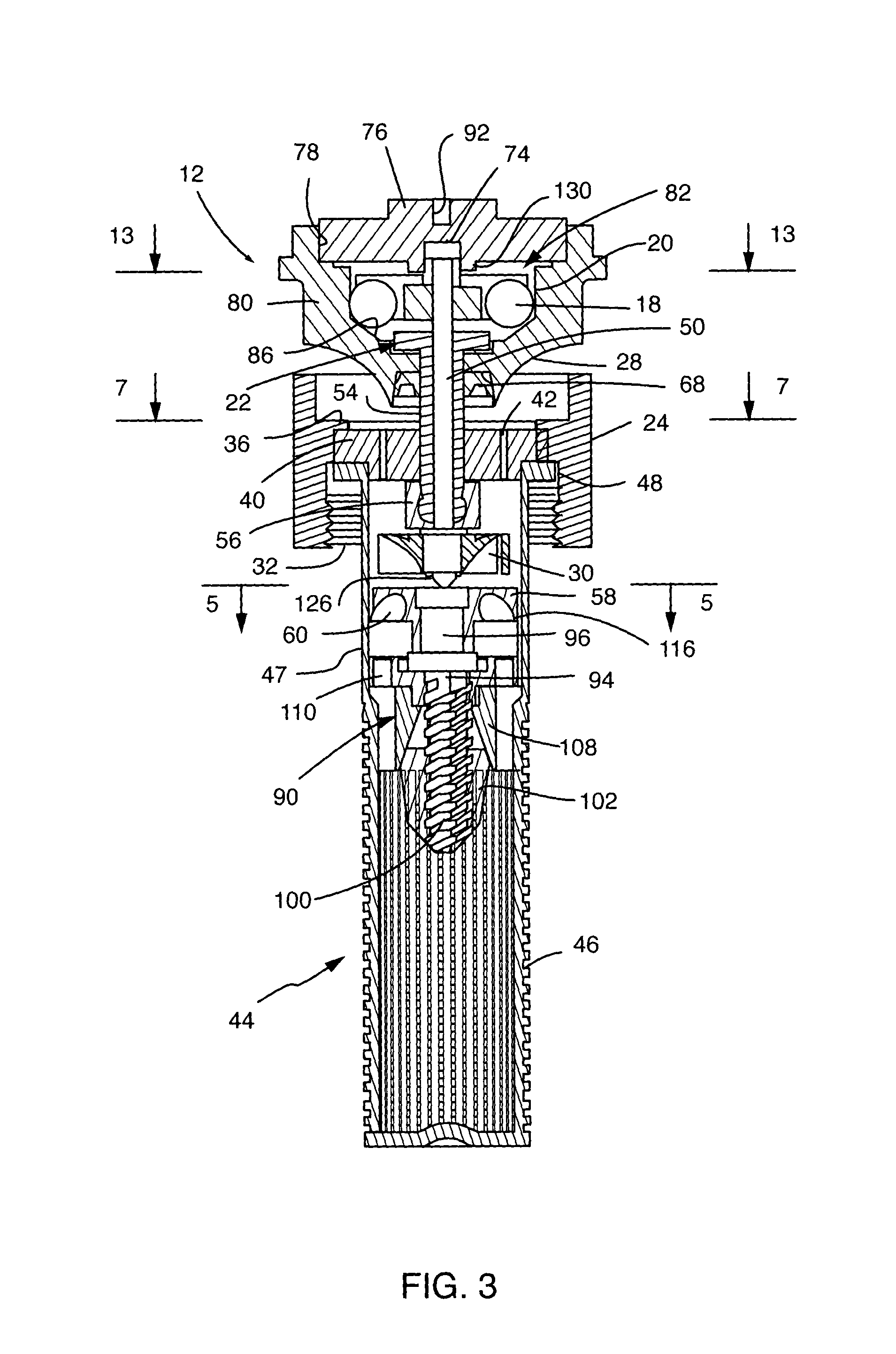
[0030]As shown in the exemplary drawings, a rotating stream sprinkler referred to generally in FIGS. 1–4 by the reference numeral 10 includes a vaned deflector 12 for producing and distributing a plurality of relatively small water streams 14 (FIG. 1) projected radially outwardly therefrom to irrigate a surrounding terrain area. The deflector 12 is rotatably indexed in a rapid succession of relatively small angular steps or increments by a turbine driven ball drive rotor 16 (FIGS. 3, 4 and 12–14) including one or more drive balls 18 for repetitious impact engagement with one or more anvils 20 carried by the deflector. A speed control brake 22 (FIG. 3) is additionally provided to maintain the rotational speed of the deflector 12 at a controlled, relatively slow, and substantially constant speed throughout a range of normal operating pressures and flow rates.

[0031]The rotating stream sprinkler 10 of the present invention generally comprises a compact sprinkler nozzle unit or head havi...


PUM


Abstract

A rotating stream sprinkler of the type having a rotatable vaned deflector for stepwise sweeping of relatively small water streams over surrounding terrain to irrigate adjacent vegetation. The sprinkler includes a turbine driven ball drive rotor having at least one drive ball carried by centrifugal force into repetitious impact engagement with one or more raised anvils on the deflector for incrementally displacing the deflector in a succession of small rotational steps. A speed control brake includes a brake pad interposed between a friction surface on the deflector and a nonrotating brake disk to provide a variable friction force to maintain deflector rotation substantially constant within a range of normal water supply pressures and flow rates.

Description

BACKGROUND OF THE INVENTION[0001]This invention relates generally to improvements in irrigation sprinklers of the so-called micro-stream type having a rotatably driven vaned deflector for sweeping a plurality of relatively small water streams over a surrounding terrain area to irrigate adjacent vegetation. More specifically, this invention relates to an improved rotating stream sprinkler having a ball drive rotor for rotatably driving the deflector in a succession of relatively small angular increments or steps, in combination with a speed control brake for maintaining the rotational speed of the vaned deflector substantially constant throughout a range of normal operating pressures and flow rates.[0002]Rotating stream sprinklers, sometimes referred to as micro-stream sprinklers, are well known in the art of the type for producing a plurality of relatively small outwardly projected water streams swept over surrounding terrain. In one common form, one or more jets of water are direct...

Claims


Application Information

Patent Timeline
Patent Type & Authority Patents(United States)
IPC IPC(8): B05B3/04B05B3/00B05B3/02B05B1/34B05B1/30B05B3/16B05B15/10
CPCB05B3/003B05B3/16B05B3/0486B05B3/0404B05B15/10B05B15/74
Inventor DE LOS SANTOS, LINO
Owner RAIN BIRD CORP
Learn More