
Multi-mode smart card, system and associated methods

a smart card and multi-mode technology, applied in the field of information processing and storage, can solve the problems of credit card numbers being stolen, not using sc technology, and limited die size for mechanical aspects

Inactive Publication Date: 2005-04-26
STMICROELECTRONICS SRL +1
View PDF8 Cites 135 Cited by
  • Summary
  • Abstract
  • Description
  • Claims
  • Application Information

AI Technical Summary

Benefits of technology

The present invention provides an integrated circuit that can selectively operate in more than one protocol, allowing it to communicate with different devices using different protocols. This is achieved by configuring the IC in the appropriate mode based on the detected protocol during a power-on reset sequence. The IC can detect and configure in either an ISO mode or a non-ISO mode, and can only operate in the mode it is configured in without changing it unless another power-on reset sequence is performed. The system using this IC includes an ISO-compliant reader and a non-ISO-compliant reader, and the method involves detecting the mode of the device and configuring the IC accordingly.

Problems solved by technology

The die size is limited for mechanical aspects going with the plastic nature of the SC.
The many users share the cost of the SC reader.
False credit card numbers are used, credit card numbers are stolen and eavesdropping on the Internet is well established.
On the other hand, the Internet, a formidable arena to enhance commerce and Banking activities, does not use the SC technology.
Most of the Internet transactions are done from a PC and despite PC manufacturer efforts, the PC industry has failed to install on each PC a cost effective SC reader meeting the specific needs of web related applications.
However, the mode signal is not checked until after the smart card is powered up and the reset signal has been applied.

Method used


Image

  • Multi-mode smart card, system and associated methods
  • Multi-mode smart card, system and associated methods
  • Multi-mode smart card, system and associated methods

Examples


Embodiment Construction

[0053]The present invention will now be described more fully hereinafter with reference to the accompanying drawings, in which preferred embodiments of the invention are shown. This invention may, however, be embodied in many different forms and should not be construed as limited to the embodiments set forth herein. Rather, these embodiments are provided so that this disclosure will be thorough and complete, and will fully convey the scope of the invention to those skilled in the art. Like numbers refer to like elements throughout.

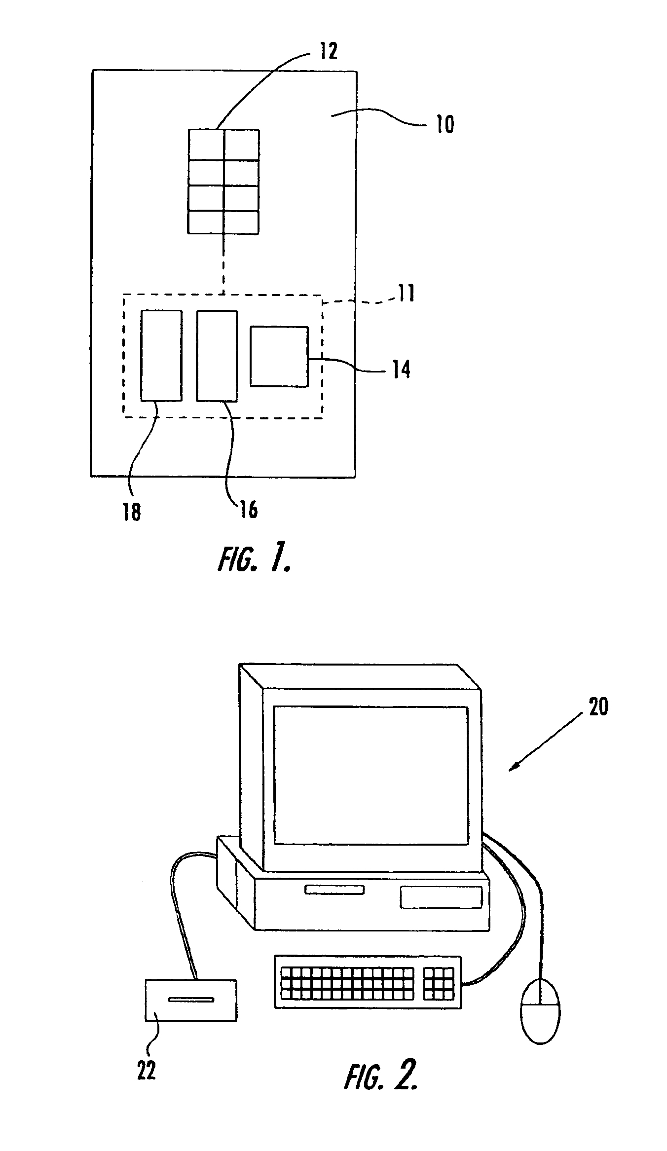
[0054]Referring to FIG. 1, a smart card 10 in accordance with the present invention will now be described. The smart card 10 is made of plastic, for example, and has a plurality of electrical contacts or pads 12 on an outer surface thereof, as would be appreciated by those skilled in the art. As shown, the card 10 includes eight pads 12, for example. The pads 12 are the external interface for the integrated circuit (IC) 11 which is embedded within the card...


PUM


Abstract

A multi-mode IC is provided for operating in a first mode such as an ISO mode in accordance with International Standards Organization 7816 (ISO 7816) protocol, and a second, non-ISO mode, such as a USB mode in accordance with Universal Serial Bus (USB) protocol. The multi-mode IC is preferably in a smart card and includes a microprocessor and an external interface. The external interface comprises a voltage supply pad, a ground pad, a first set of pads for the first mode, and 2 second set of pads for the second mode. The first set of pads preferably include a reset pad, a clock pad and an input / output pad in accordance with the ISO 7816 protocol, and may also include a variable supply voltage pad in accordance with the ISO 7816 protocol. The IC further includes a mode configuration circuit for detecting a mode condition on one pad of the first set of pads, and configuring the IC in the ISO mode or the non-ISO mode depending on the result. Once the IC is configured in a particular mode, it will operate in only that mode until the next power-on reset sequence.

Description

FIELD OF THE INVENTION[0001]The present invention relates to information processing and storage, and more particularly, to smart card systems.BACKGROUND OF THE INVENTION[0002]Smart cards (SC) are plastic cards having an embedded Integrated Circuit (IC). That IC may be a logic circuit with its associated memories or a microcontroller with its associated memories and software, or a microcontroller with its associated memories and software coupled to a custom block.[0003]To use the computing power given by the IC, a SC makes use of a full set of packaging technologies. The die size varies from 1 mm2 to 30 mm2. The die size is limited for mechanical aspects going with the plastic nature of the SC. The IC is attached to a lead frame and wire-bonding techniques are used to connect the IC pads to the lead frame contacts. Potting and other strengthening methods protect the IC against chemical and mechanical stresses. Contacts are located on one side of the card and their number is limited t...

Claims


Application Information

Patent Timeline
Patent Type & Authority Patents(United States)
IPC IPC(8): G06K19/07G06K17/00G06F13/10
CPCG06K19/07G06K19/07733G06K19/0712G06K19/0707
Inventor FRUHAUF, SERGE F.POMET, ALAIN CHRISTOPHELEYDIER, ROBERT ANTOINE
Owner STMICROELECTRONICS SRL
Learn More