
Logging insertion/removal of server blades in a data processing system

Inactive Publication Date: 2005-04-19
IBM CORP
View PDF18 Cites 20 Cited by
  • Summary
  • Abstract
  • Description
  • Claims
  • Application Information

AI Technical Summary

Problems solved by technology

In this environment, it is frequently difficult for system administrators to keep track of the location of individual server blades and how many times a server blade has been inserted into a rack.
Determining the warranty periods of individual blades can quickly prove formidable if the location of each blade is not carefully maintained.
If blade movement within a system is not tracked, a server blade may be inserted more times than permitted by the blade specification thereby potentially resulting in faulty operation and / or the denial of warranty benefits by the manufacturer.

Method used


Image

  • Logging insertion/removal of server blades in a data processing system
  • Logging insertion/removal of server blades in a data processing system
  • Logging insertion/removal of server blades in a data processing system

Examples


Embodiment Construction

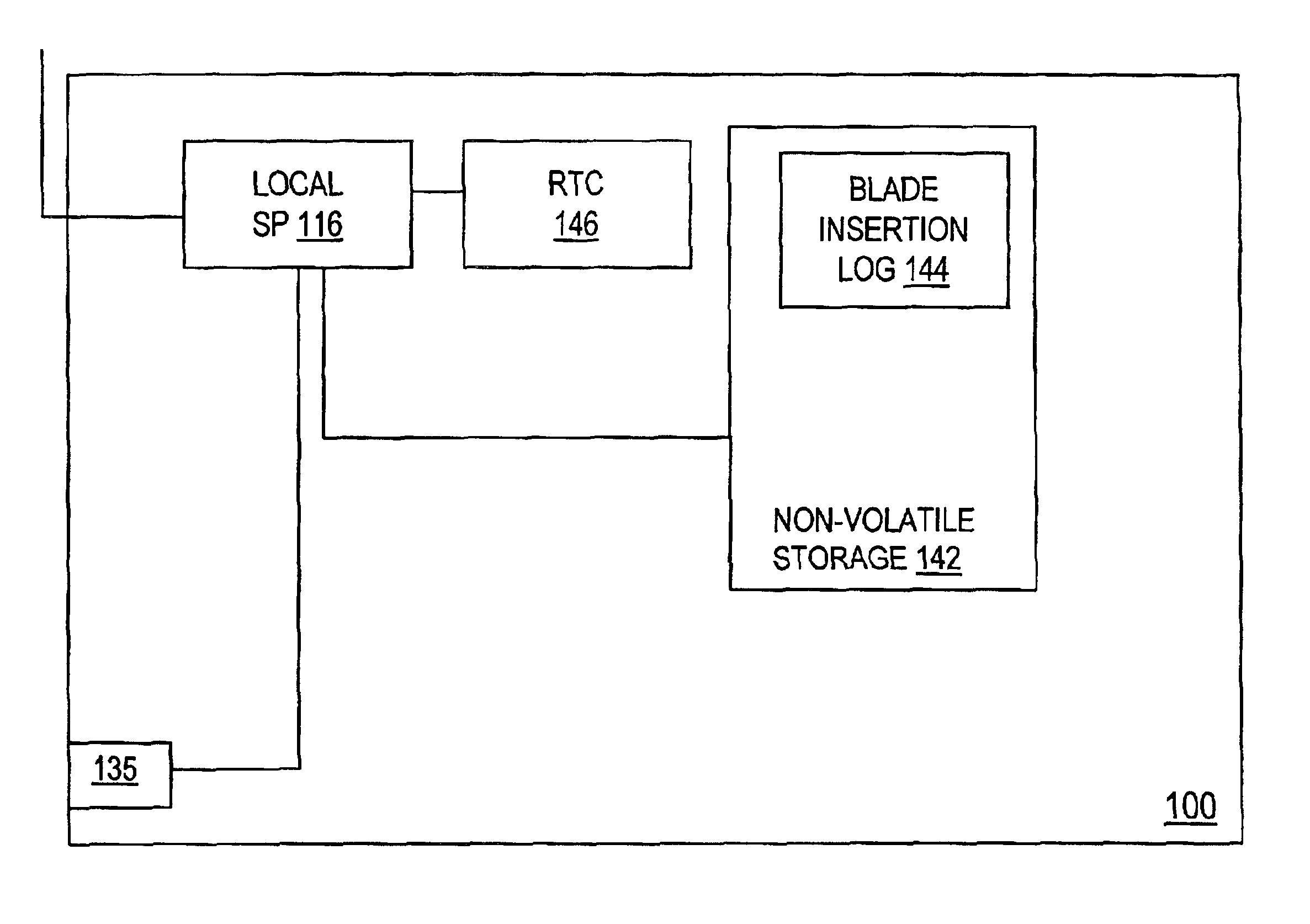
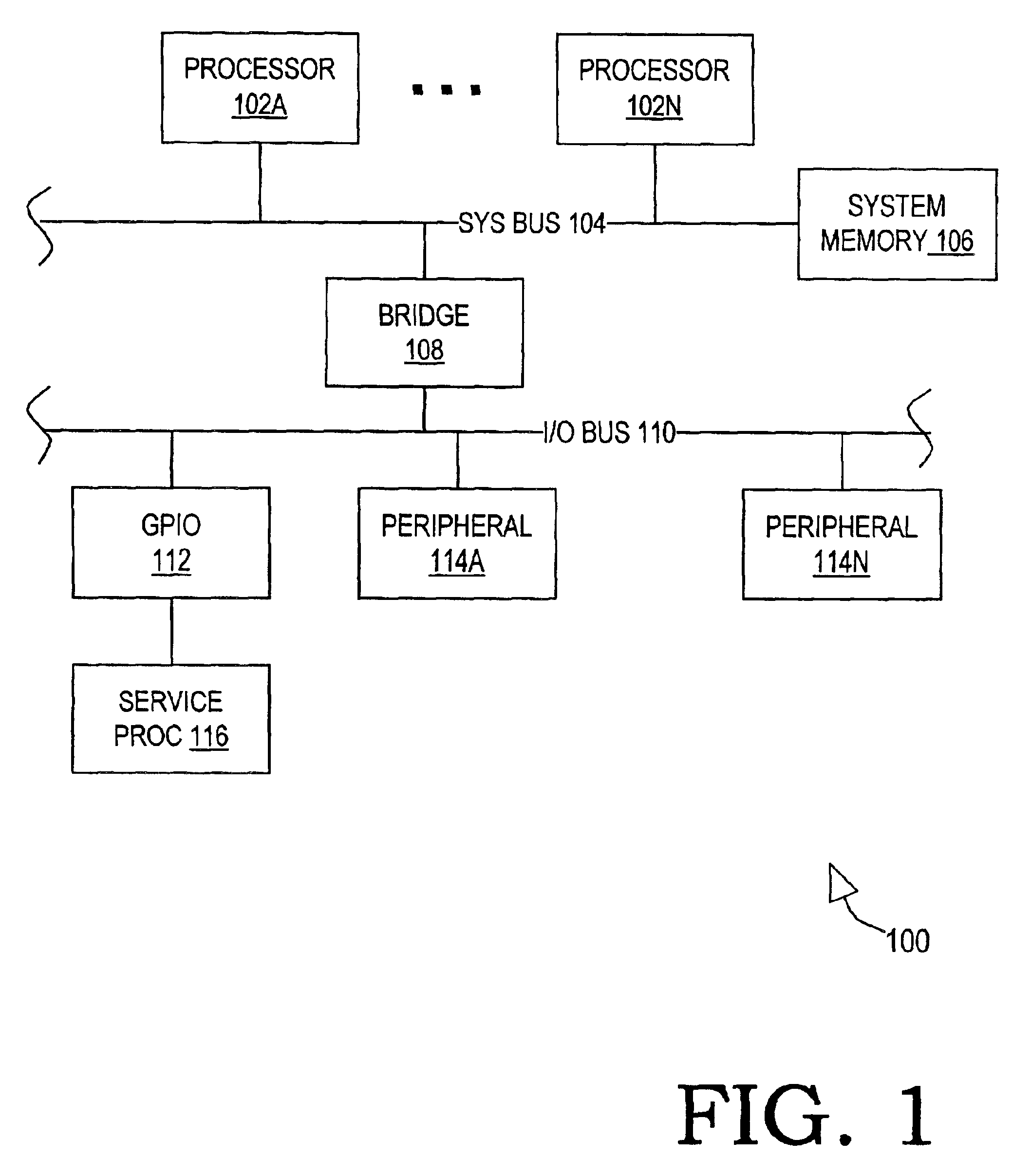
[0015]Turning now to the drawings, FIG. 1 is a block diagram of selected features of a data processing system 100 suitable for implementing the present invention. Data processing system 100 may be implemented entirely upon a single printed circuit board. In this embodiment, data processing system 100 may be alternatively referred to herein as server blade 100. In the depicted embodiment, server blade 100 includes a set of main processors 102A through 102N (generically or collectively referred to as processor(s) 102) that are connected to a system bus 104. A common system memory 106 is accessible to each processor 102 via system bus 104. The system memory is typically implemented with a volatile storage medium such as an array of dynamic random access memory (DRAM) devices. The depicted architecture of server blade 100 is frequently referred to as a symmetric multiprocessor (SMP) system because each processor 102 has substantially equal access to system memory 106.

[0016]In server bla...


PUM


Abstract

This invention is comprised of a data processing system containing at least one main processor connected to a system bus, a system memory connected to the system bus and accessible to each of the main processors, a tamper mechanism, and a local service processor. The tamper mechanism is configured to change state each time the system is inserted into a slot in a rack enclosure. The local service processor is connected to the tamper mechanism and configured to update an insertion log upon detecting a change in state of the tamper mechanism. The insertion log provides a count and a history of rack insertions to which the system has been subjected. The system may include a non-volatile storage element which is updated exclusively by the local service processor that contains the insertion log. The insertion log may include an insertion counter. In this embodiment, the local service processor is configured to increment the insertion counter upon each insertion. The local service processor may be further configured to issue an alert if the insertion counter exceeds a predetermined value. In one embodiment, the system further includes a battery backed real-time clock connected to the local service processor. The local service processor is configured to include real-time information corresponding to each insertion event in the insertion log. Each entry in the insertion log may include the identity of the rack enclosure and the geographical address of the slot of the corresponding insertion event. The local service processor may be configured to detect the tamper mechanism state and update the insertion following a power event such that the insertion log update is independent of configuring the data processing system with a boot image.

Description

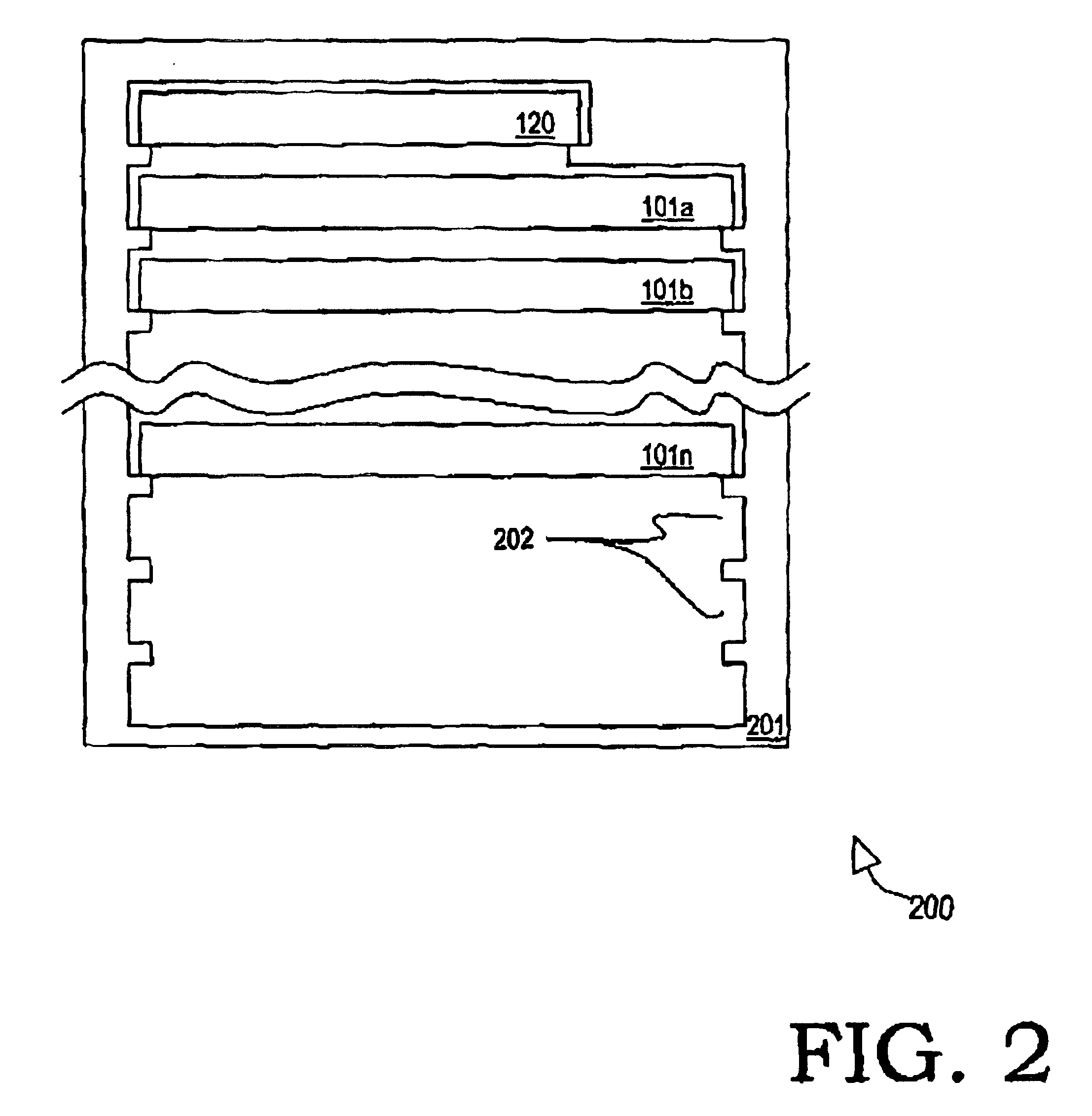
BACKGROUND[0001]1. Field of the Present Invention[0002]The present invention generally relates to the field of data processing systems and more particularly to a system and method for logging the insertion and removal of circuit boards or blades in a data processing system.[0003]2. History of Related Art[0004]Data processing systems in general and server-class systems in particular are frequently implemented with a server chassis or cabinet having a plurality of racks. Each cabinet rack can hold a rack mounted device (also referred to herein as a blade or server blade) on which one or more general purpose processors and / or memory devices are attached. The racks are vertically spaced within the cabinet according to an industry standard displacement (the “U”). Cabinets and racks are characterized in terms of this dimension such that, for example, a 42U cabinet is capable of receiving 42 1U rack-mounted devices, 21 2U devices, and so forth. Dense server designs are also becoming availa...

Claims


Application Information

Patent Timeline
IPC IPC(8): G06F21/00G06F21/86
CPCG06F21/86G06F2221/2101
Inventor ABBONDANZIO, ANTONIOCHU, SIMON C.DAKE, GREGORY WILLIAMHOLLAND, WILLIAM GAVINPIAZZA, WILLIAM JOSEPHPRUETT, GREGORY BRIANRHOADES, DAVID B.
Owner IBM CORP
Learn More