
Raman amplifier

a technology of amplifier and amplifier, applied in the field of optical amplifier, can solve the problems of not being able to suppress gain deviation below 1 db regarding the operating band width of 30 nm, and the achievement of higher speed is approaching to its limit, and achieves the effect of worsening the gain flatness

Inactive Publication Date: 2005-04-19
FURUKAWA ELECTRIC CO LTD
View PDF35 Cites 13 Cited by
  • Summary
  • Abstract
  • Description
  • Claims
  • Application Information

AI Technical Summary

Benefits of technology

[0018]Further, another object of the present invention is to provide a Raman amplifier suitable for compensating Raman effect between signals which arises a problem during wide band WDM transmission.
[0019]In the present invention, it is also considered to provide a Raman amplifier in which, when a gain band is expanded by adding new pump light, gain and gain flatness after expansion are not deteriorated considerably in comparison with before expansion.
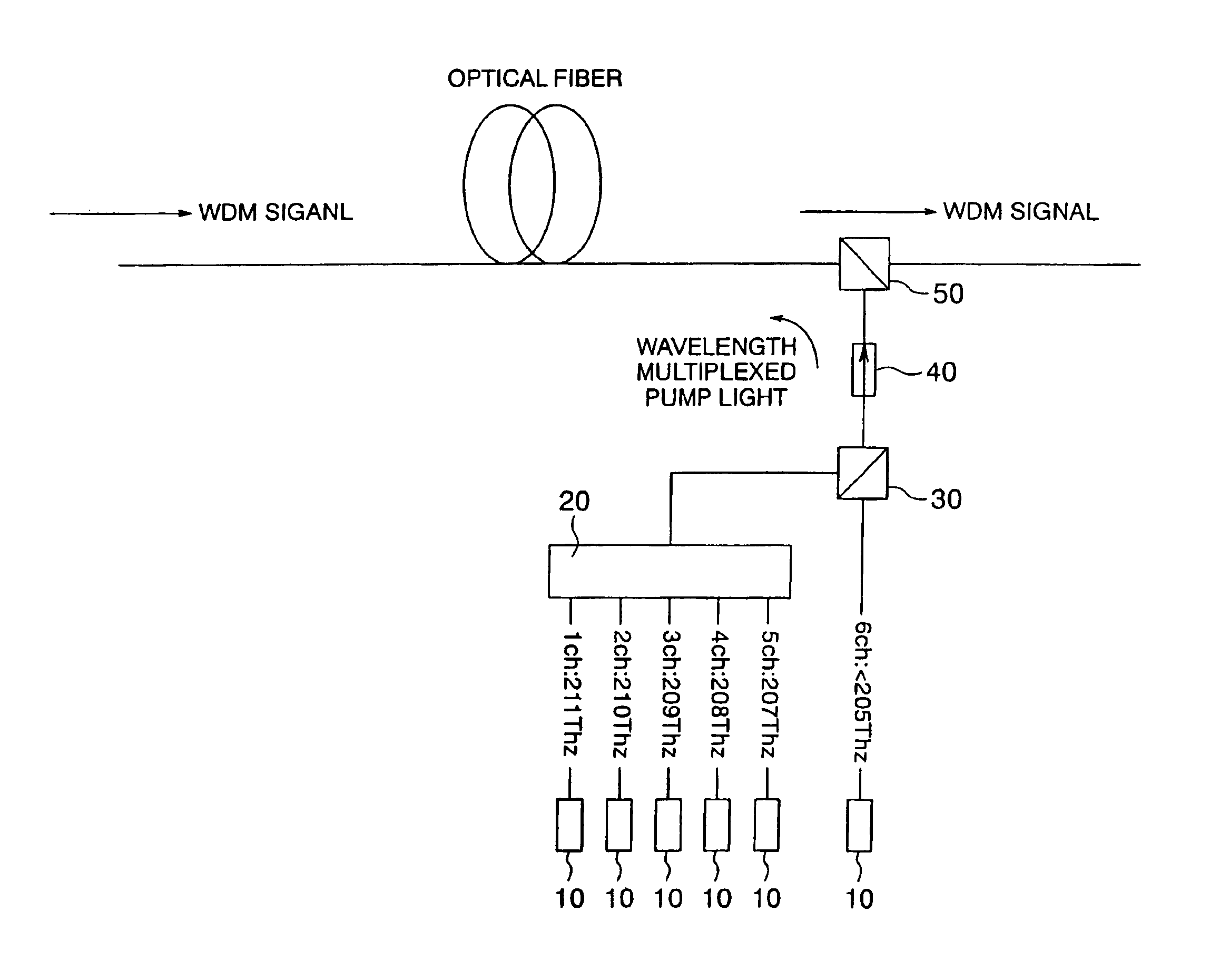
[0032]While the effects as mentioned above was explained for the purpose of reducing the gain flatness, by reducing the gain of the pump light at the long wavelength side, a gain profile in which gain is linearly reduced from the short wavelength side toward the long wavelength side can be achieved. When this is combined with the tilt of optical signal level created by the Raman effect between the optical signals, the level of the optical signal can be flattened. Since any tilt can be realized by adjusting the distribution of gain between the short wavelength side and the long wavelength side, any Raman tilt can be compensated for.
[0034]However, when both the pump lights for C-band and L-band shown in FIGS. 26 and 27 are simultaneously used, gain profiles such as shown in FIG. 31 are obtained even if the gain allocation is optimized so as to be flatten. The following Table 5 pumping wavelengths used in this case. In this case, if the gain flatness is tried to be equal to those shown in FIGS. 26 and 27 in the entire area of C+L as shown in FIG. 31, a big recess is generated in the C-band, thereby more worsening the gain flatness than before expansion.

Problems solved by technology

However, in systems utilizing a discrete amplifier such as EDFA, achievement of higher speed has been approaching to its limit.
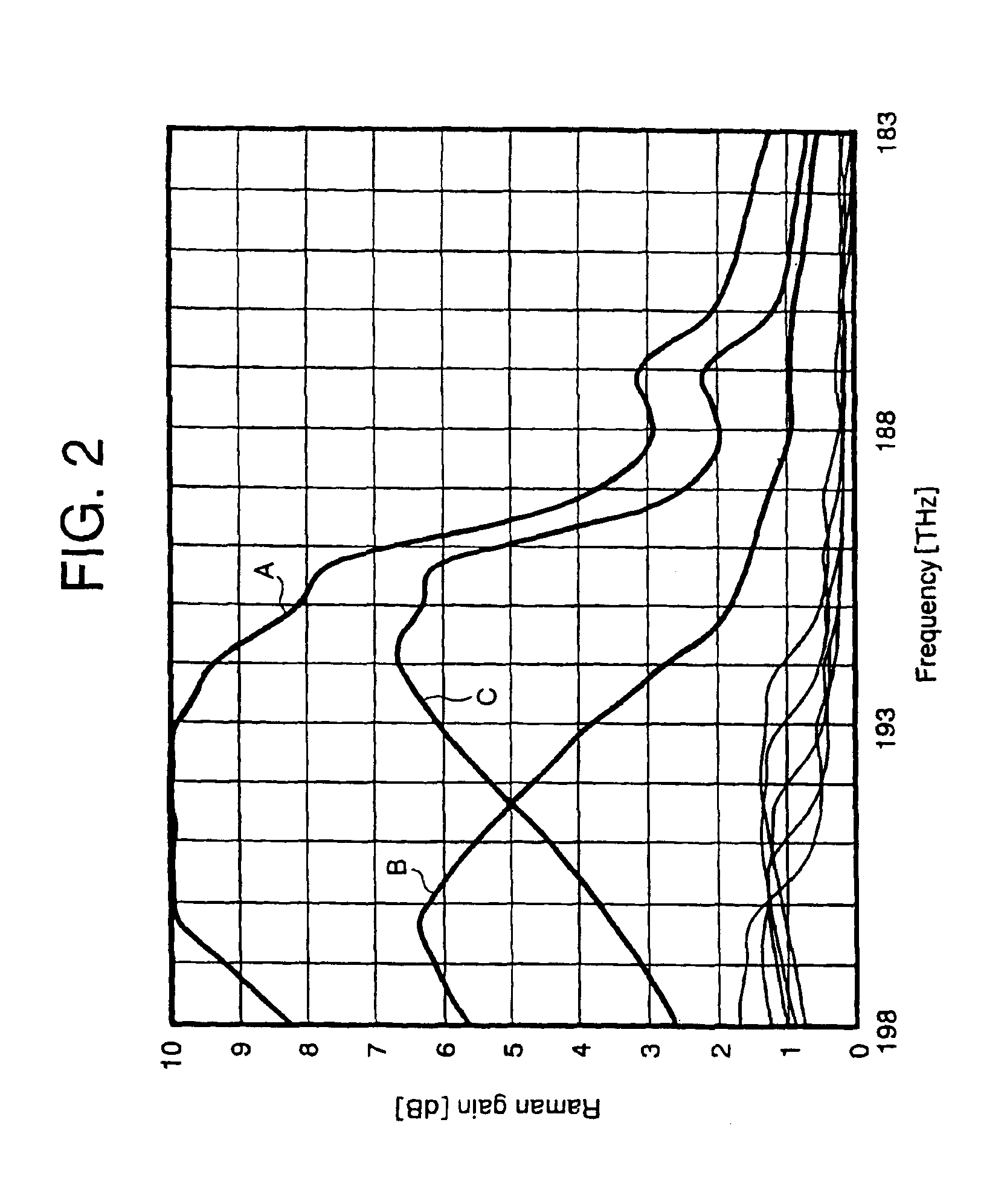
However, single wavelength pumped Raman gain has great wavelength dependency, and as apparent from FIG. 22, from when the Raman gain exceeds about 5 dB, it is impossible to suppress gain deviation below 1 dB regarding an operating band width of 30 nm.
That is to say, these examples show the fact that the gain flatness is not so good if the pump light interval becomes more than 35 nm.
However, considering conversely, it can be said that, even when the wavelength interval is included in the range, if the wavelength interval is not set properly, flat gain cannot be obtained.
However, as the used band of the optical signal is increased, there arose a problem regarding Raman amplifying effect between optical signals.
Further, as mentioned above, in a case where the pump lights are equidistantly arranged, even when the wavelength interval is smaller than 35 nm, the gain deviation may not be reduced sufficiently.
Although the gain deviation can be reduced by reducing the pump light interval in principle, due to problems regarding a wave combining technique and cost, practically, the pump light interval has a lower limit.
Further, in the design described in a published paper (Y. Emori et al, OFC'99 PD19), the gain deviation is 1 dB, and this technique cannot be applied when smaller gain flatness is required.

Method used


Image

  • Raman amplifier
  • Raman amplifier
  • Raman amplifier

Examples


example 1

[0086]Now, the Raman amplifier according to the present invention will be explained in connection with an example that the band is expanded to C+L band by combining the C band and the L band. FIG. 17 shows an example that the pump light has two wavelengths before expansion, and there are pumping wavelengths before and after expansion, as shown in the following Table 6. By selecting one of pumping wavelengths added for the expansion to 1439 nm, at least one of the pump lights added for the expansion is located within the band of the pump lights (1426 nm to 1453 nm) before expansion. Due to the presence of such pump light, the expansion can be realized while maintaining the gain flatness.

[0087]

TABLE 6Pumpingwavelength [nm]After expansionBefore expansionAddition1426∘∘1439∘∘1453∘∘1464∘∘1493∘∘

[0088]FIG. 18 shows an example that the pump light has three wavelengths before expansion, and there are pumping wavelengths before and after expansion, as shown in the following Table 7. By selecti...

example 2

[0092]This example 2 shows an example that the pump light has two wavelenghts before expansion and the wavelength of the pump light before expansion is greater than that in the example 1. In this example, the gain band for the C band is designed to be 1535 nm to 1570 nm. The pumping wavelenghts before and after expansion are as shown in the Table 9. By selecting one of pumping wavelengths added for the expansion to 1444 nm, at least one the pump lights added for the expansion is located within the band of the pump lights (1430 nm to 1457 nm) before expansion. Due to the presence of such pump light, the expansion can be realized while maintaining the gain flatness.

[0093]

TABLE 9Pumpingwavelength [nm]After expansionBefore expansionAddition1430∘∘1444∘∘1457∘∘1464∘∘1493∘∘

example 3

[0094]This example 3 shows an example that the pump light has two wavelengths before expansion and the wavelength of the pump light before expansion is smaller than that in the example 1. In this example, the gain band of the C band is designed to be 1525 nm to 1560 nm. The pumping wavelengths before and after expansion are as shown in the following Table 10. By selecting one of pumping wavelengths added for the expansion to 1438 nm, at least one of the pump lights added for the expansion is located within the band of the pump lights (1422 nm to 1450 nm) before expansion. Due to the presence of such pump light, the expansion can be realized while maintaining the gain flatness.

[0095]

TABLE 10Pumpingwavelength [nm]After expansionBefore expansionAddition1422∘∘1438∘∘1450∘∘1464∘∘1493∘∘


PUM


Abstract

In a Raman amplifier using three or more pumping wavelengths, when the pumping wavelengths are divided into a short wavelength side group and a long wavelength side group at the boundary of the pumping wavelength having the longest interval between the adjacent wavelengths, the short wavelength side group includes two or more pumping wavelengths having intervals therebetween which are substantially equidistant, and the long wavelength side group is constituted by two or less pumping wavelengths. When a certain pumping wavelength is defined as a first channel and pumping wavelengths which are spaced apart from each other by about 1 THz from the certain pumping wavelength toward a long wavelength side are defined as second to n-th channels, respectively, pump lights having wavelengths corresponding to the first to n-th channels are multiplexed, and pump light having a wavelength spaced apart from the n-th channel by 2 THz or more toward the long wavelength side is further multiplexed with the said multiplexed pump light, and resultant pump light is used as pump source. Pump lights of all of the wavelengths corresponding to the channels other than (n−1)th and (n−2)th channels are multiplexed with each other, and resultant pump light is used as pump source. Pump lights of all of the wavelengths corresponding to the channels other than (n−2)th and (n−3)th channels are multiplexed with each other, and resultant pump light is used as pump source.

Description

BACKGROUND OF THE INVENTION[0001]1. Field of the Invention[0002]The present invention generally relates to an optical amplifier, and, more particularly, it relates to a Raman amplifier.[0003]2. Description of the Related Art[0004]In wavelength division multiplexed (WDM) systems used in current optical communication systems, as methods for increasing transmission capacity, there are a method for expanding a signal wavelength band to increase the number of multiplexed wavelengths, and a method for enhancing a transmission rate (bit rate) per wavelength. In normal WDM systems, due to limitation in gain wavelength band of an Erbium doped fiber amplifier (EDFA), most generally, a wavelength for optical signal is selected from a wavelength band (called as a C-band) of about 1530 to 1565 nm. On the other hand, since optical amplification can be effected by the EDFA also in a wavelength band (called as an L-band) of about 1575 to 1610 nm, recently, WDM systems regarding this band has been d...

Claims


Application Information

Patent Timeline
Patent Type & Authority Patents(United States)
IPC IPC(8): H01S3/30H04B10/17H01S3/094H01S3/23H04B10/291
CPCH01S3/302H04B10/2916H01S3/094096H01S2301/04H01S3/06766H01S3/09408H01S3/0677H01S3/10007H01S3/1001
Inventor EMORI, YOSHIHIRONAMIKI, SHU
Owner FURUKAWA ELECTRIC CO LTD
Learn More