
Synchronization of hardware simulation processes

a hardware simulation and simulation process technology, applied in the field of electronic system design, can solve the problem of consuming clock credit, and achieve the effect of fast and efficient manner

Inactive Publication Date: 2005-04-12
HEWLETT-PACKARD ENTERPRISE DEV LP +1
View PDF15 Cites 16 Cited by
  • Summary
  • Abstract
  • Description
  • Claims
  • Application Information

AI Technical Summary

Benefits of technology

The invention described herein can provide clock signals of different rates to different clock domains of an individual DUT during simulation. The invention has the additional feature of being able to create a test bench that manages inputs and outputs specifically for a particular DUT during simulation. The invention has the additional feature of being able to simulate a system of DUT...

Problems solved by technology

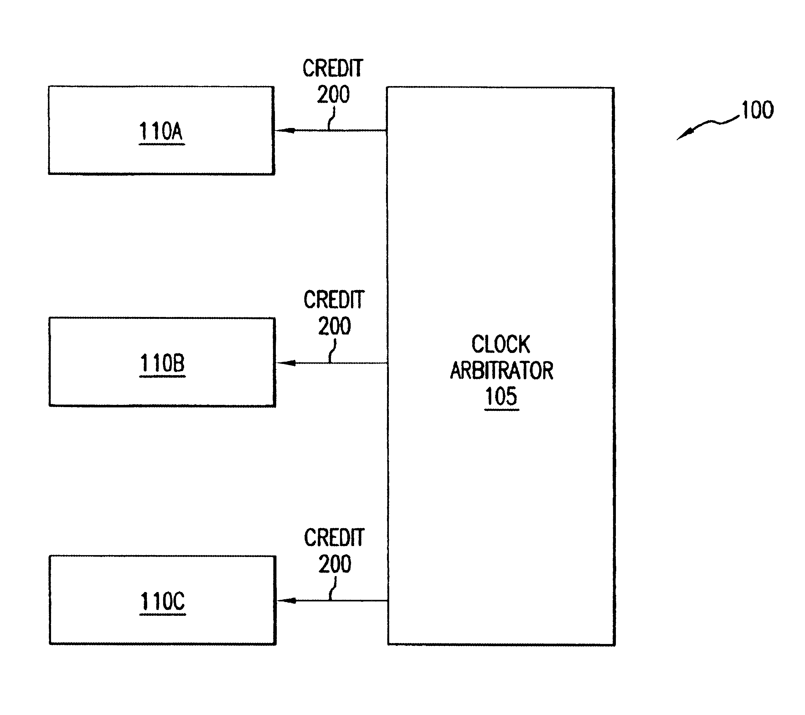
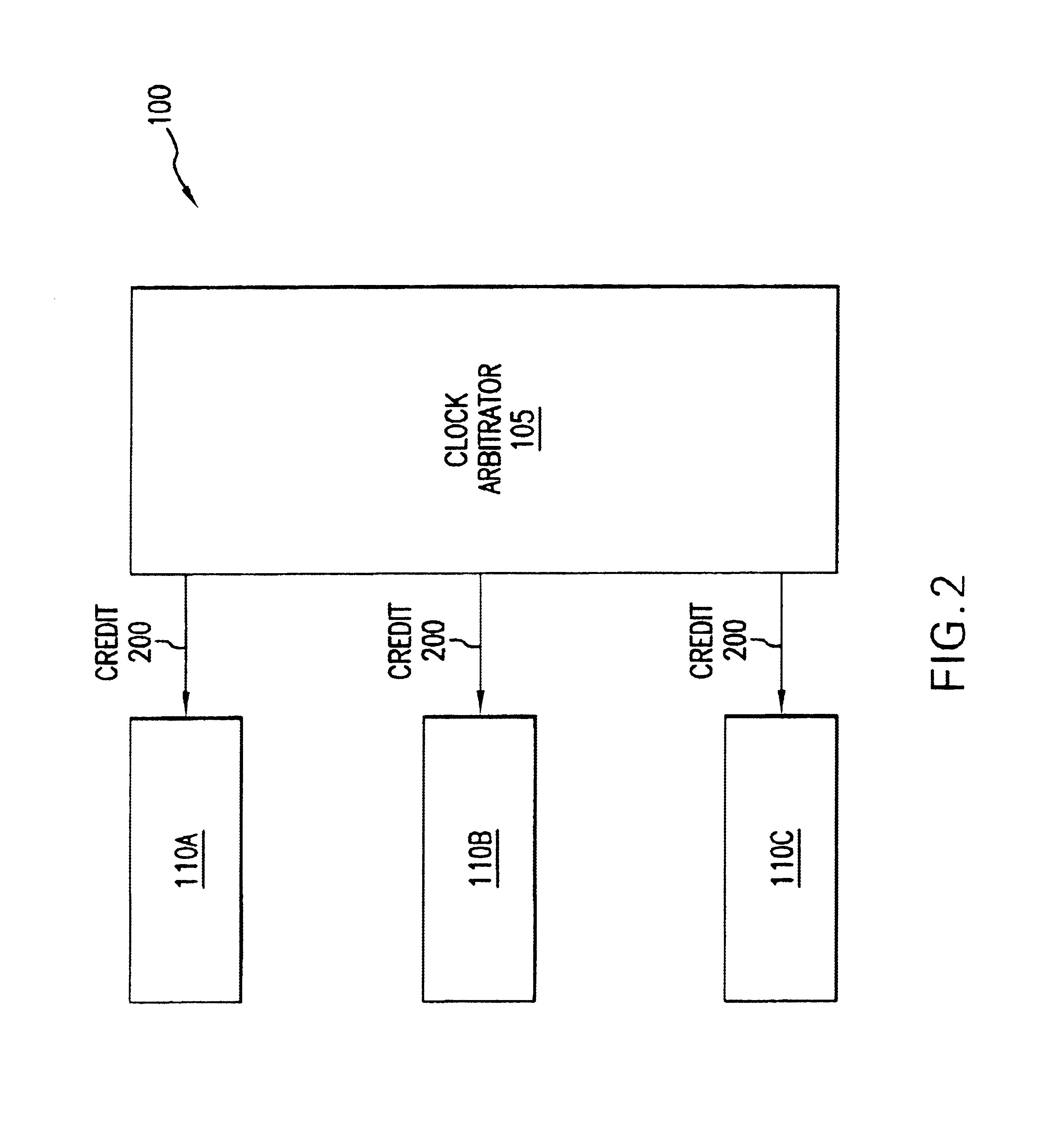
Operation is said to consume the clock credit.

Method used


Image

  • Synchronization of hardware simulation processes
  • Synchronization of hardware simulation processes
  • Synchronization of hardware simulation processes

Examples


Embodiment Construction

A preferred embodiment of the present invention is now described with reference to the figures where like reference numbers indicate identical or functionally similar elements. Also in the figures, the left most digit of each reference number corresponds to the figure in which the reference number is first used. While specific configurations and arrangements are discussed, it should be understood that this is done for illustrative purposes only. A person skilled in the relevant art will recognize that other configurations and arrangements can be used without departing from the spirit and scope of the invention. It will be apparent to a person skilled in the relevant art that this invention can also be employed in a variety of other devices and applications.

Contents

I. TerminologyII. OverviewIII. SystemIV. MethodV. EnvironmentVI. Conclusion

I. Terminology

The following section defines several terms that occur frequently throughout the application.

VERILOG is a language for simulation of ...


PUM


Abstract

A system, method, and computer program product is presented for simulating a system of hardware components. Each component is simulated in a hardware definition language such as VERILOG. Each component is represented as a simulated device under test (DUT) that is incorporated into a simulation module. The invention synchronizes the simulation modules by issuing clock credit to each simulation module. Each simulation module can only operate when clock credit is available, and can only operate for some number of clock cycles corresponding to the value of the clock credit. Operation is said to consume the clock credit. After a simulation module has consumed its clock credit, its DUT halts. Once every simulation module has consumed its clock credit and halted, another clock credit can be issued. This allows checkpointing of the operation of each DUT and simulates parallelism of the DUTs using executable images of manageable size. A given DUT can include two or more subsets of logic that each require a clock signal having a different rate. Such subsets of the logic of a DUT are referred to as clock domains. The appropriate clock signals are created by a test bench component of the simulation module. The test bench creates a master clock signal for the DUT. The test bench then divides this clock signal to produce clock signals applied to the clock domains of the DUT. The test bench can be created through automated means by providing a system specification that defines the inputs (including clocks) and outputs of a DUT. This allows a test bench specific to the DUT to be created.

Description

BACKGROUND OF THE INVENTION1. Field of the InventionThe present invention pertains to electronic system design, and more particularly to the simulation of digital circuitry.2. Related ArtThe process of designing and testing digital circuitry typically includes software simulation of the circuitry. Simulation takes place prior to development of a physical prototype, and allows economical testing of the logic of a circuit. Test vectors serve as inputs to the simulated circuitry, and the outputs are analyzed as a way of verifying the accuracy of the design.A problem arises when a large amount of circuitry needs to be simulated. Simulation of a large circuit requires a large executable image, which can exceed the memory capacity of a simulation environment. Simulation of a system of circuits, such as a system of interoperating chips that perform in parallel, leads to the same problem. Current simulation methods deal with the image size problem by simulating a subset of the circuitry in ...

Claims


Application Information

Patent Timeline
IPC IPC(8): G06F17/50
CPCG06F17/5022G06F30/33
Inventor CHALFIN, ALEXDAUDEL, JEFFREYGROSSMAN, MARKMUKHERJEE, SHRIJEETOSTRIN, PETERREDD, JARRETT
Owner HEWLETT-PACKARD ENTERPRISE DEV LP
Learn More