
Pool cleaning vehicle having improved logic

a technology of logic and cleaning vehicle, which is applied in the direction of swimming pools, filtration separation, and separation processes, etc., can solve the problems of slowing down the cleaning of the pool, affecting the cleaning efficiency of the pool, and at least a little adversely, so as to achieve a fast and efficient manner of cleaning

Inactive Publication Date: 2011-03-03
SMARTPOOL
View PDF2 Cites 24 Cited by
  • Summary
  • Abstract
  • Description
  • Claims
  • Application Information

AI Technical Summary

Benefits of technology

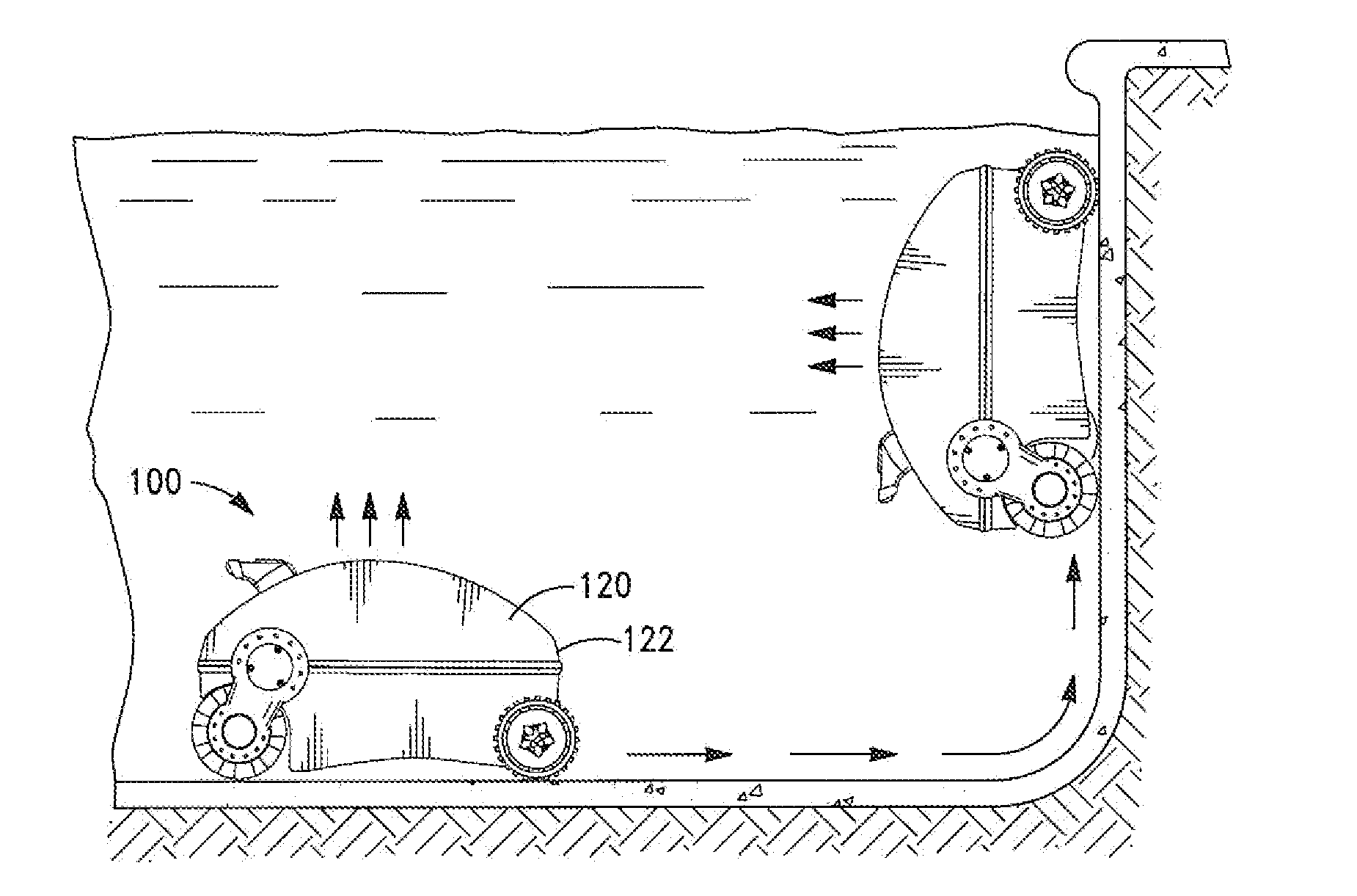
[0011]It is an object of the pool cleaning device in accordance with this invention to provide a cleaning vehicle having logic means for causing the vehicle to move about the surface of the pool, including the upright walls, in a fast and efficient manner for cleaning.
[0012]It is an additional object of the pool cleaning device in accordance with this invention to provide a pool cleaning vehicle having on-board logic means for enabling the vehicle to climb a pool wall, shut a pump within for a very short duration of time, and resume operation of the pump and travel speed.
[0040]It is an advantage of the pool cleaning vehicle in accordance with this invention to provide a vehicle for cleaning pools which does so in a more efficient manner than prior such devices.
[0041]It is also an advantage to provide such a cleaning vehicle, which provides for improved efficiency in cleaning, while having a single speed motor.

Problems solved by technology

While, for typical known pool cleaning devices, this may or may not be effective, the net result is to slow down the cleaning of the pool.
So ironically, the very thing that Porat is attempting to solve, namely, time efficient cleaning of the pool, is, at least, somewhat adversely affected by the proposed solution.
In Porat's defense, it must be said that the de-stabilization of the device would be more time costly than merely slowing down the device.

Method used


Image

  • Pool cleaning vehicle having improved logic
  • Pool cleaning vehicle having improved logic
  • Pool cleaning vehicle having improved logic

Examples


Embodiment Construction

[0047]To better illustrate the objects and advantages of the pool cleaning vehicle in accordance this invention, a detailed description of the drawing is provided below. As will be appreciated by those skilled in the art, the exemplary embodiments are provided for explanation only and are not to be for purposes of limiting the scope of the invention.

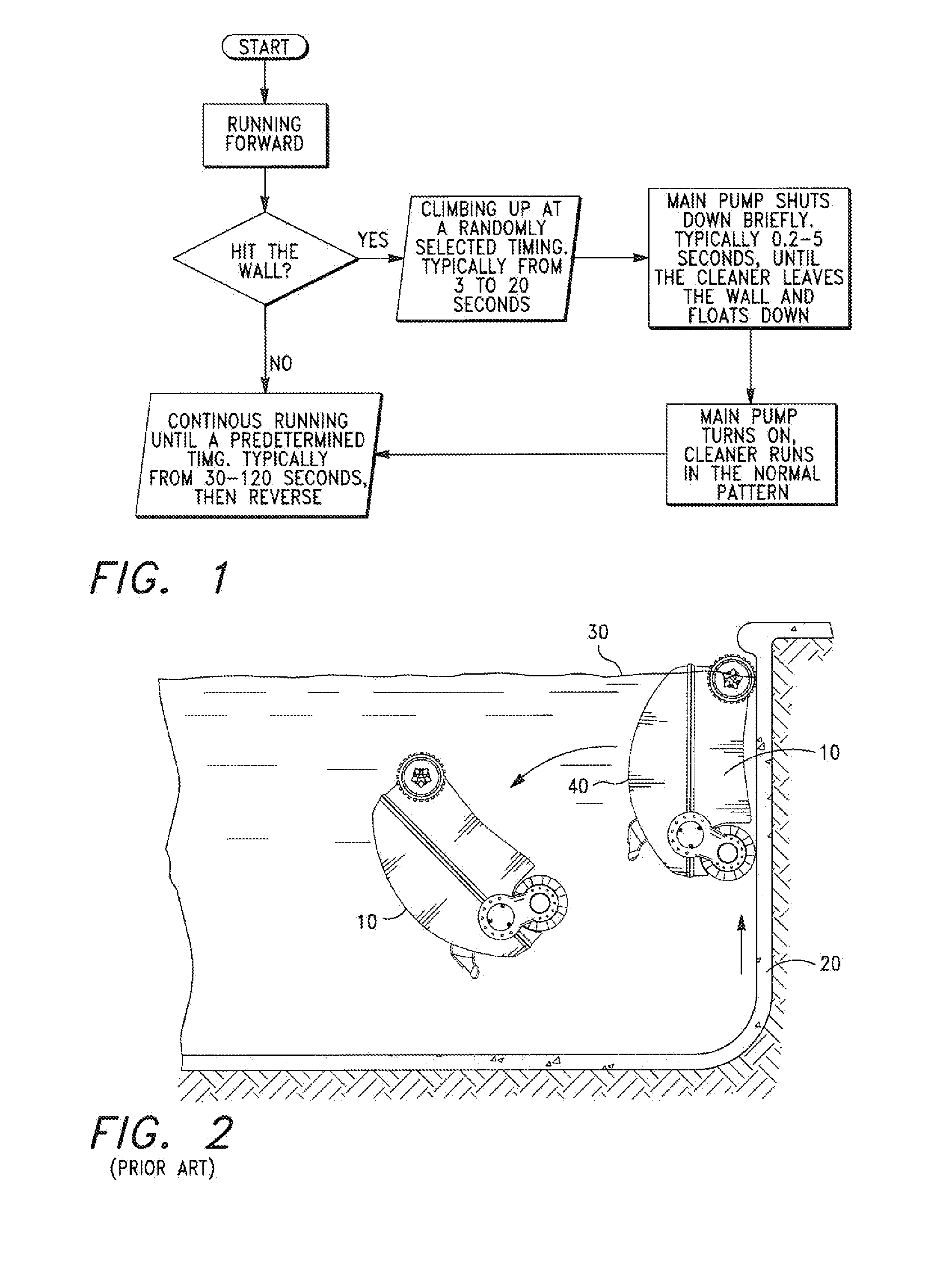
[0048]FIG. 1 illustrates a schematic of the logic, which forms an integral part of the structure of the pool cleaning vehicle in accordance this invention.

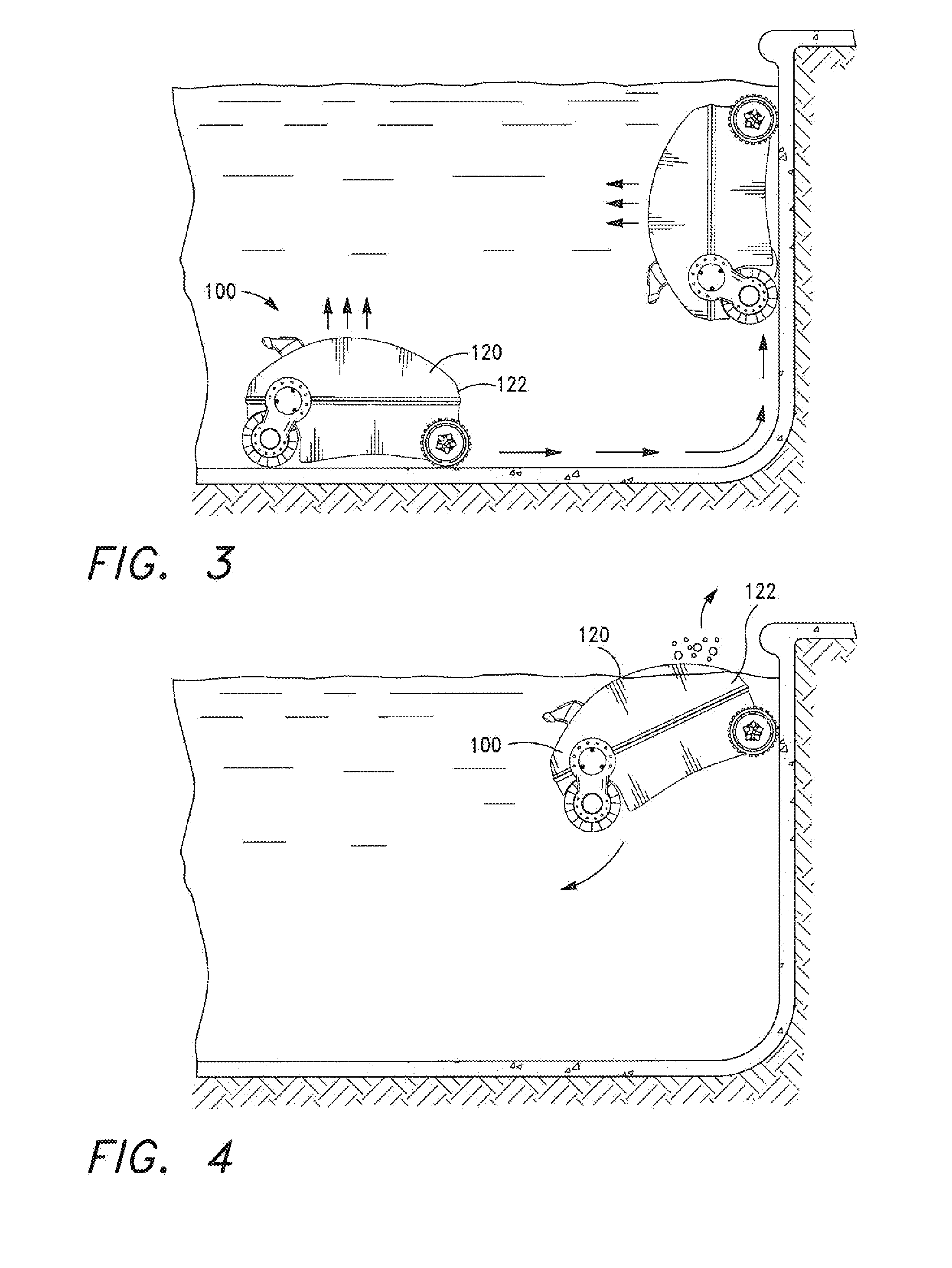
[0049]FIG. 2 has been previously described and as noted above illustrates a typical prior art device reaching and even breaking the surface of the pool water. Thereafter, as illustrated, the pool cleaning device becomes de-stabilized. In this case, the de-stabilization causes the device to turtle, rolling over on its back. In the turtle position, the user must make manual correction. Quite clearly, the normal operation of cleaning the pool is interrupted, delayed and intervention by th...


PUM

PropertyMeasurementUnit
timeaaaaaaaaaa
timeaaaaaaaaaa
timeaaaaaaaaaa

Abstract

A swimming pool cleaning vehicle is disclosed herein. The vehicle includes a housing and the housing having a body shell and a frame and an interior with the housing. The housing, having an outlet, for releasing air from the shell. The shell being removable attached to the frame, the frame including a base. The vehicle including a filtration system having a pump motor for pumping pool water through filtration system, the pump creating a suction force, the suction force being sufficient to allow the vehicle to climb the pool walls. The vehicle capable of climbing the pool walls. And, the vehicle capable of breaking the surface of the water as it climbs pool walls. The vehicle including logic means for first, initiating vehicle movement, second, shutting off pump, and third, re-starting pump. And, the logic means causing the pump to operate at a first primary speed, shutting off the pump upon reaching a predetermined distance in relation to the surface of the water, returning the pump to the first primary speed after shut off.

Description

RELATED PATENT APPLICATIONS[0001]This application is relates to three other of Applicant's filings, which are filed concurrently with this application. Those filings are Attorney Docket No. JHUI1951, JHUI1952 and JHUI1946. Upon receiving serial numbers for all three cases, Applicant will amend this section of the application to include those serial numbers. Additionally, each of those applications is specifically incorporated in full in this application, as if they were word for word written here. They are incorporated in full for all purposes.FIELD OF THE INVENTION[0002]This invention relates to the field of pool cleaning devices and more particularly to domestic or industrial swimming pool cleaners. More particularly, this invention relates to those pool cleaners that are wall climbing and capable of breaking the surface of the water with their own propulsion.TECHNICAL BACKGROUND[0003]As noted in earlier patents, notably Porat U.S. Pat. No. 6,099,658, it is increasingly important ...

Claims


Application Information

Patent Timeline
Patent Type & Authority Applications(United States)
IPC IPC(8): E04H4/16
CPCE04H4/1654
Inventor HUI, WING-KIN
Owner SMARTPOOL
Learn More