Permanent magnet rotor electrical synchronous machine with different alternatively arranged tooth pitch widths

a permanent magnet rotor and electrical synchronization technology, which is applied in the direction of windings, salient poles, magnetic circuit shapes/forms/construction, etc., can solve the problems of further cost saving, and achieve the effect of low stator production costs and high machine utilization

Inactive Publication Date: 2005-04-12
SIEMENS AG
View PDF13 Cites 21 Cited by
  • Summary
  • Abstract
  • Description
  • Claims
  • Application Information

AI Technical Summary

Benefits of technology

The object of the present invention is to provide an electrical synchronized machine, particularly for three-phase applications, which results in low stator production costs while at the same time providing high machine utilization with the magnetic fields having an approximately sinusoidal profile. This object is achieved by an electrical synchronized machine having the following features:a stator and a rotor with the stator having a three-phase winding and the roto...

Problems solved by technology

There is, therefore, no need to provide any phase intermediate la...

Method used


Image

  • Permanent magnet rotor electrical synchronous machine with different alternatively arranged tooth pitch widths
  • Permanent magnet rotor electrical synchronous machine with different alternatively arranged tooth pitch widths
  • Permanent magnet rotor electrical synchronous machine with different alternatively arranged tooth pitch widths

Examples


Embodiment Construction

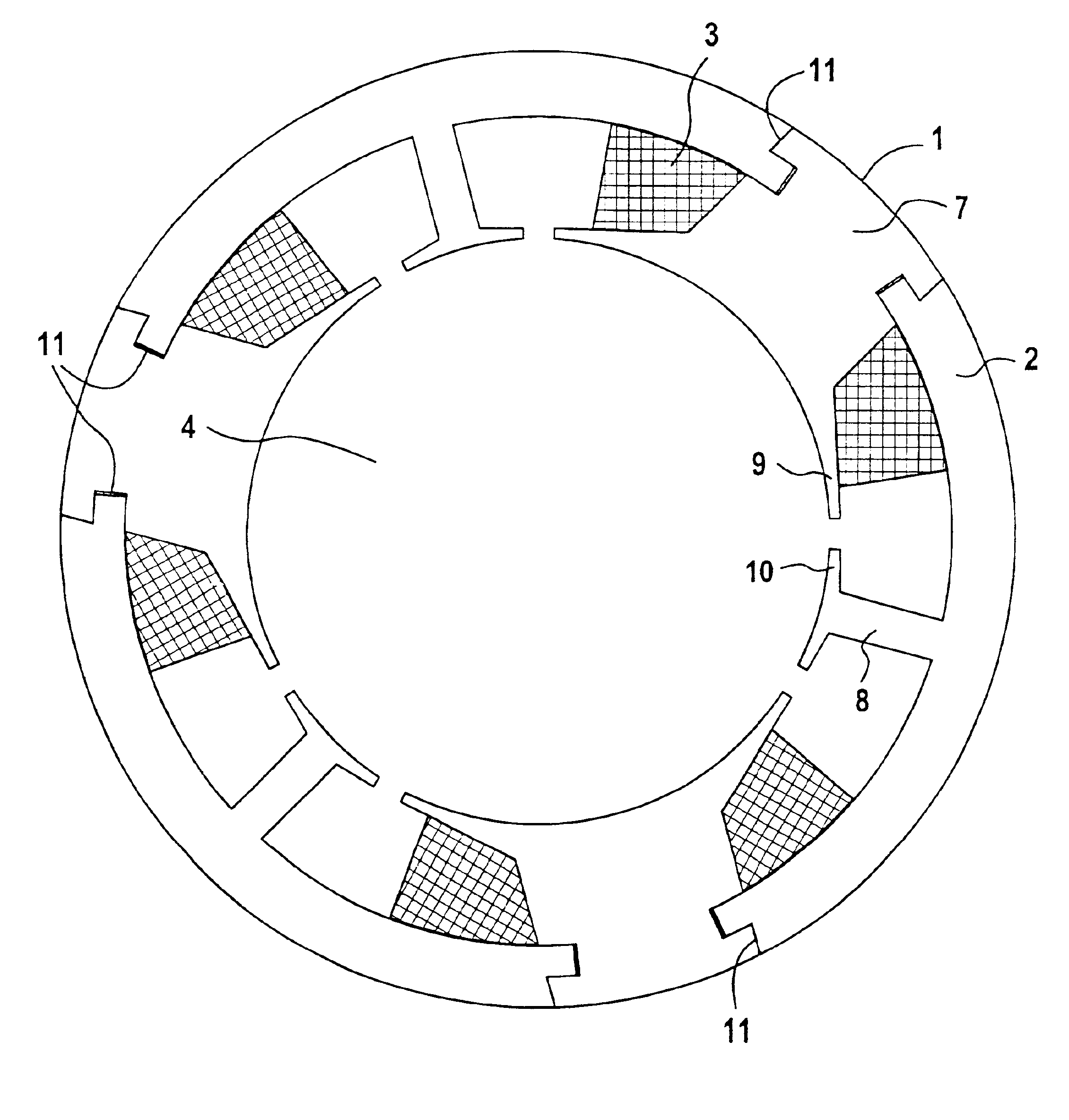
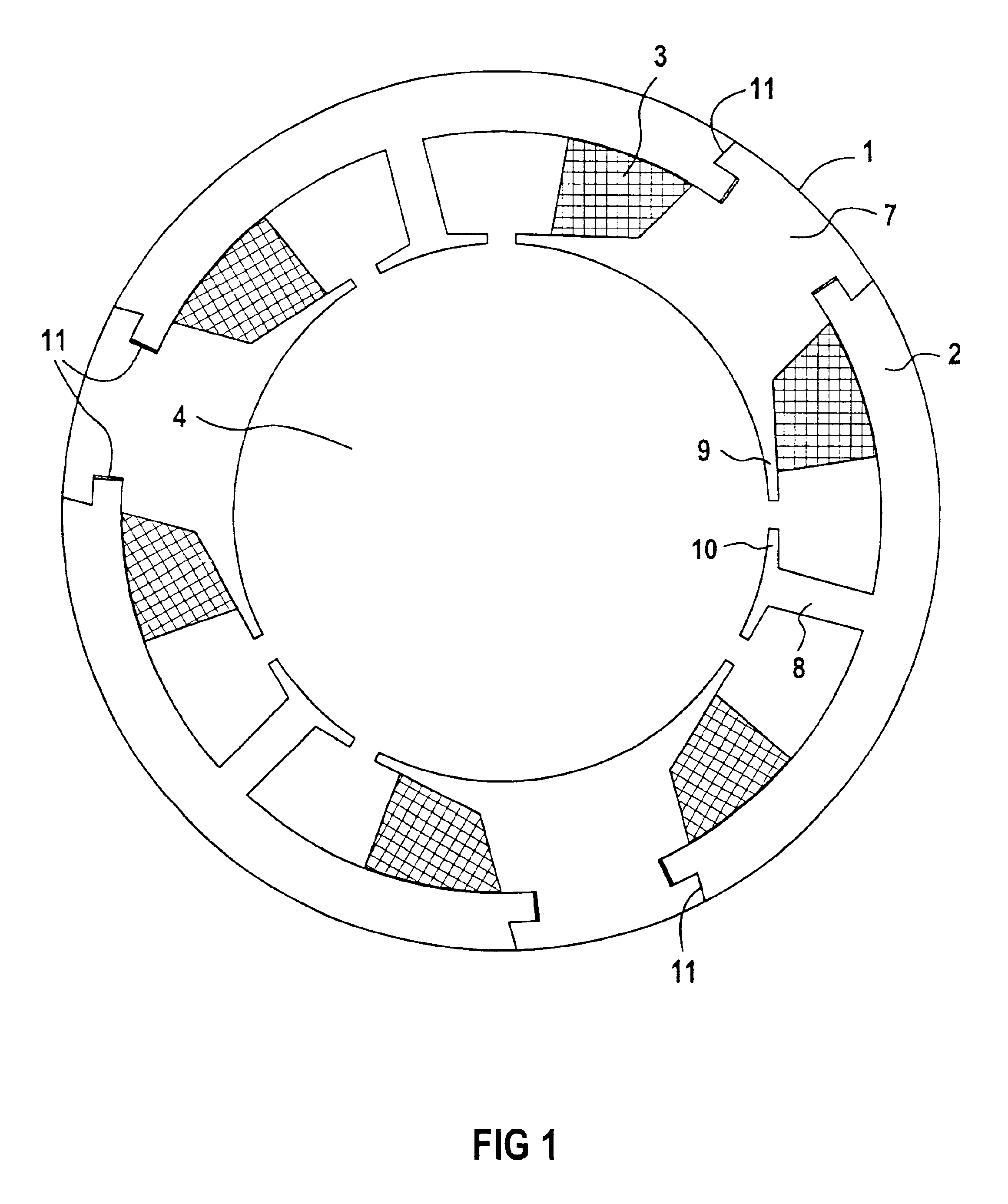
FIG. 1 shows a stator which is constructed with circumferentially segments in the circumferential direction as segments 1 and 2 which, joined to one another in the circumferential direction, are attached to one another by friction and / or a positive lock and enclose the rotor bore 4. The tooth 7 of the segment 1 is in this case provided with a winding 3, which is in the form of a tooth coil. The segment 2, which contains the intermediate tooth 8, has no winding. The segments 1, 2 are joined to one another such that the magnetic reluctance at the transition point 11 increases only insignificantly.

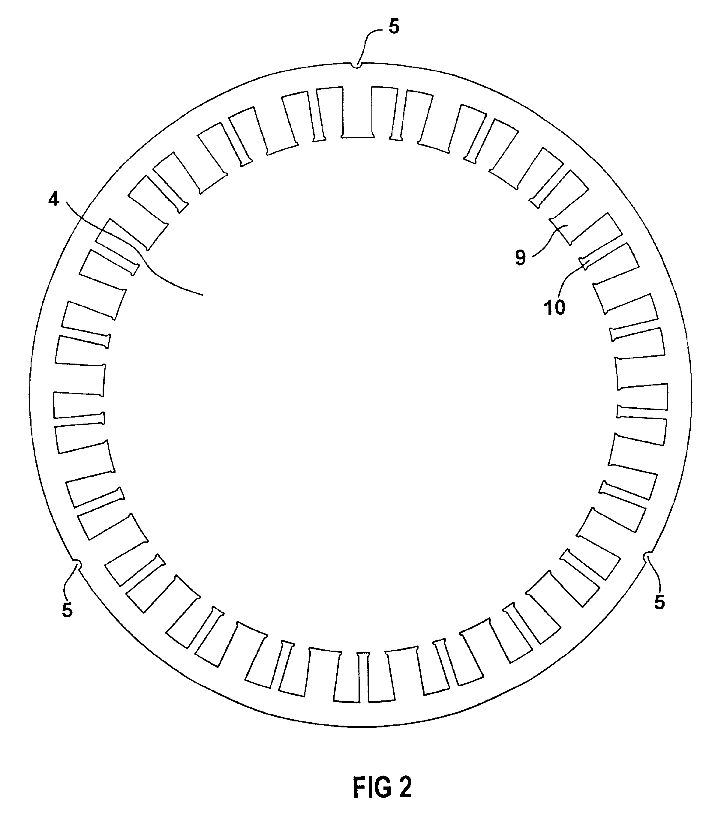
FIG. 2 shows an entire laminate section of such an electrical synchronous machine with two different tooth widths. The tooth heads 9, 10 are in this case considerably less pronounced in the direction of the airgap than in FIG. 1, making it easy to install the tooth coils. The laminate section also has cutouts 5 at the radially outer edge of the laminate section, in which corresponding holding...


PUM


Abstract

In order to achieve high machine utilization with the magnetic fields having an approximately sinusoidal profile, an electrical synchronous machine is proposed having the following features:
    • a stator and a rotor with the stator having a three-phase winding (3) and the rotor being fitted with permanent magnets,
    • the three-phase winding (3) is arranged in slots in the stator,
    • the slots in the stator are formed by essentially axially running teeth (7, 8) which have at least two different tooth pitch widths τzb and which are arranged alternately in the circumferential direction of the stator, with their number in each case being identical,
    • only the teeth (7) with a tooth pitch width which is greater than other teeth (8) are at least partially surrounded by a winding (3).

Description

FIELD OF THE INVENTIONThe invention relates to an electrical synchronous machine having a stator and a rotor, with the stator having a three-phase winding, and the rotor being fitted with permanent magnets.BACKGROUND OF THE INVENTIONA synchronous machine is a rotating AC machine, with the excitation field produced by permanent magnets in the rotor. This machine operates as a motor when its stator winding is fed with three-phase current. The rotor synchronously rotates with the rotating field, irrespective of the magnitude of the load torque. When used as a synchronous generator, this machine must be driven by a shaft, so as to convert the mechanical energy to electrical energy which is fed from the stator into the mains system. Operating in this manner has a disadvantageous affect on the torque characteristic, on the loss balance and on the noise of the synchronous machine. These drawbacks are produced, inter alia, by harmonic fields from a relatively large number of poles, which ar...

Claims


Application Information

Patent Timeline
IPC IPC(8): H02K1/14H02K21/16H02K29/03
CPCH02K1/146H02K29/03H02K21/16H02K1/148
Inventor VOLLMER, ROLF
Owner SIEMENS AG
Why Eureka
Try Eureka