
Metal tubular body and manufacturing method thereof

a tubular body and metal technology, applied in the direction of manufacturing tools, soldering devices, cathode, etc., can solve the problems of increasing the pain experienced at the time of puncture, limiting the position, shape and number of side holes in prior-art processes, and unable to form side holes anywhere other than on the bevel portion of the needle without deforming the tubular shap

Inactive Publication Date: 2005-04-12
TERUMO KK
View PDF23 Cites 13 Cited by
  • Summary
  • Abstract
  • Description
  • Claims
  • Application Information

AI Technical Summary

Benefits of technology

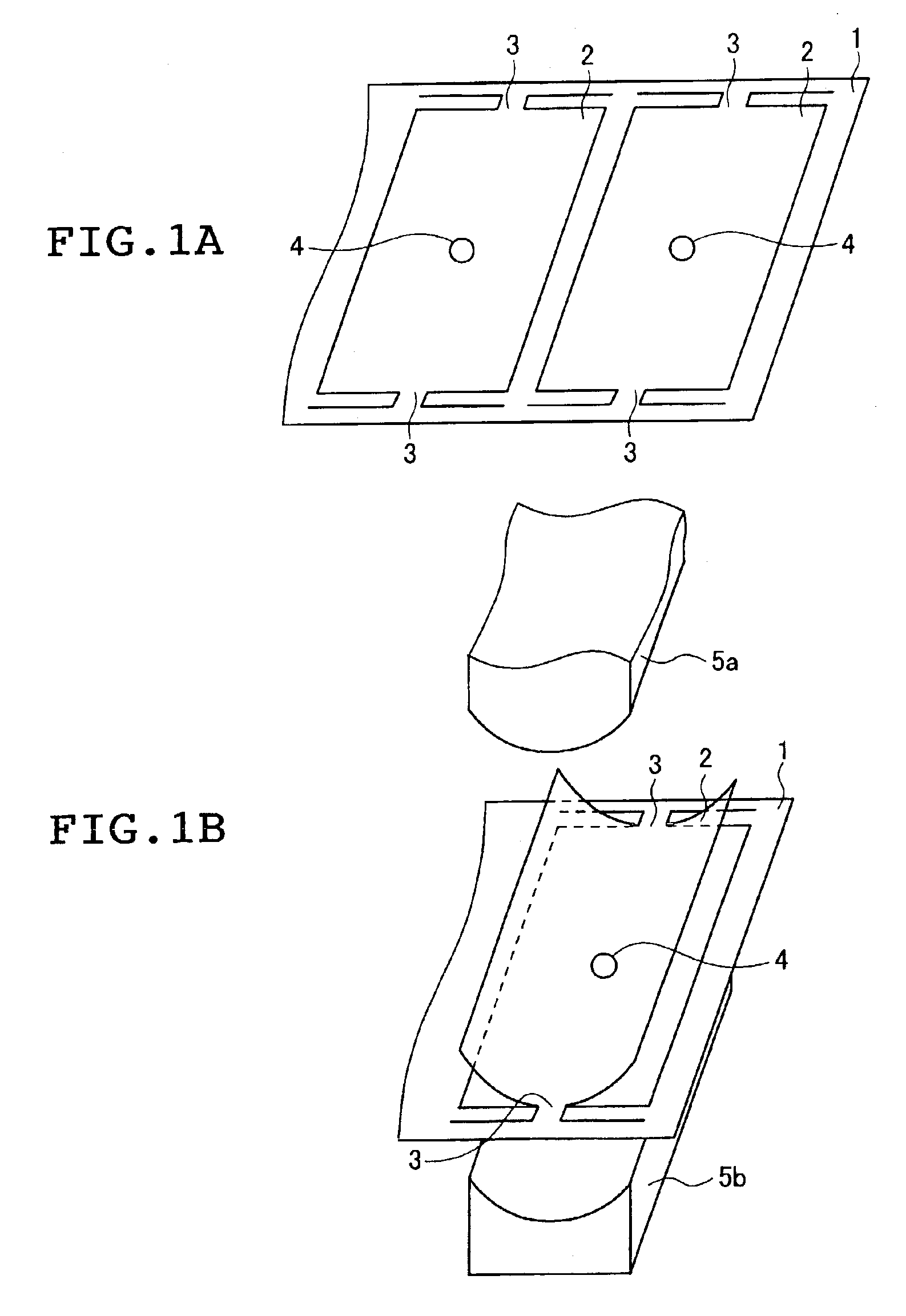
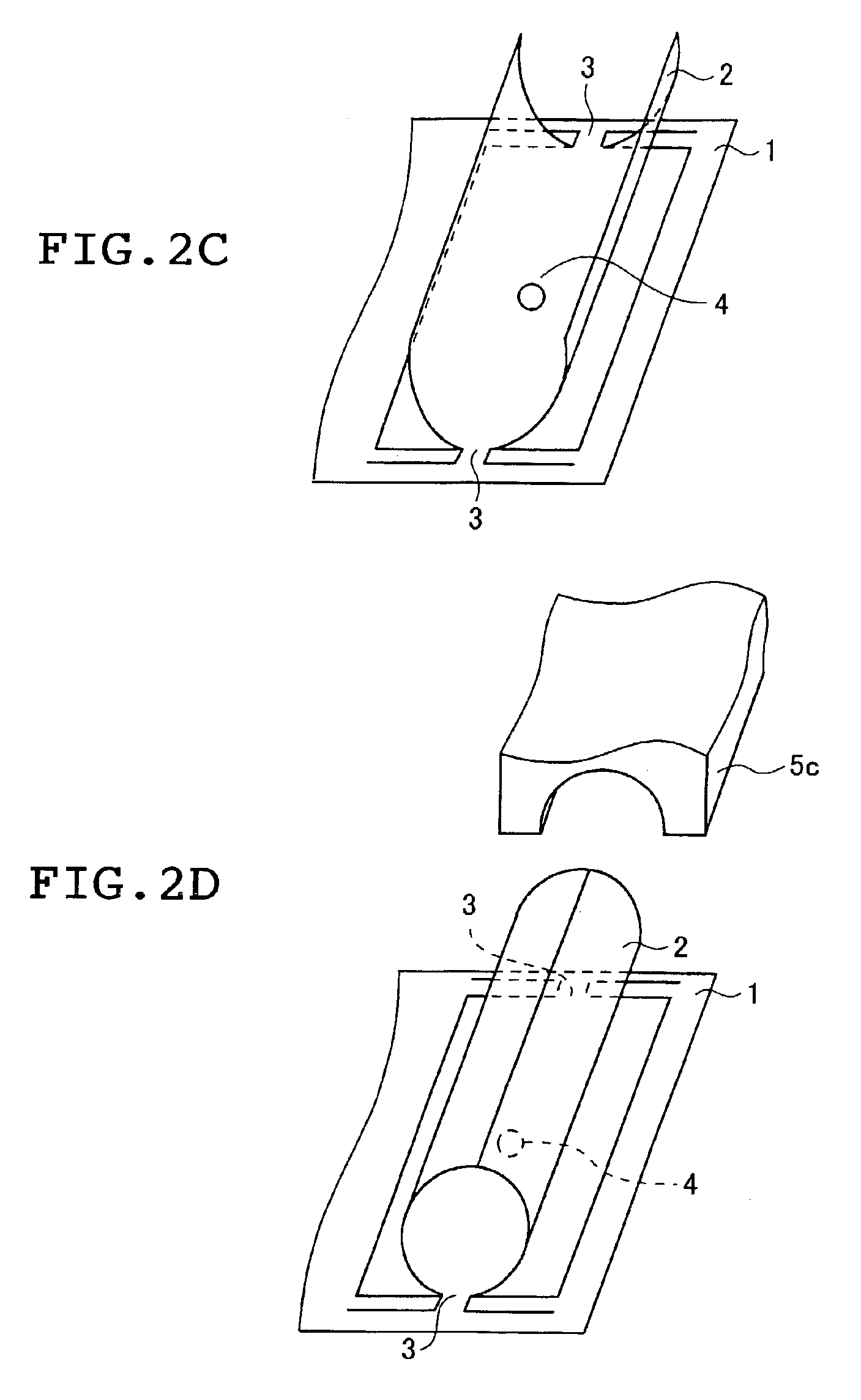
The present invention provides a method for manufacturing a metal tubular body with side holes in any desired shape, position, or number. The method involves punching a metal sheet to create a sheet blank in the shape of a tubular body, punching holes in the sheet blank to form the side holes, and then pressing the sheet blank into a tubular shape. The metal sheet and sheet blank are then cut apart. The invention also provides a metal tubular body made using this method. The technical effect of this invention is the ability to create metal tubular bodies with complex side hole configurations.

Problems solved by technology

However, indwelling needles, particularly those of a small bore, in which a side hole has been formed by such a process undergo deformation of the side hole-bearing surface when locally subjected to pressure at the side hole-forming site.
The flattened area that forms as a result increases resistance to needle penetration during a medical procedure and raises the level of pain experienced at the time of puncture.
Moreover, it has been impossible in prior-art processes to form side holes anywhere other than on the bevel portion of the needle without deforming the tubular shape.
This has limited the position, shape and number of side holes that can be formed on such needles.
Also, in the manufacture of indwelling needles by a conventional process, because the tubular body, once formed, is placed on a die and a side hole is punched therein, another drawback has been an increased number of manufacturing steps.

Method used


Image

  • Metal tubular body and manufacturing method thereof
  • Metal tubular body and manufacturing method thereof
  • Metal tubular body and manufacturing method thereof

Examples


example

The following example is provided to illustrate the invention, and is not intended to limit the scope thereof.

A 0.05 mm thick stainless steel (SUS304) sheet was subjected to pressing operations in the order shown in FIGS. 1A to 2D, thereby forming 1 mm outside diameter, 0.9 mm inside diameter, 20 mm long hollow tubes which are open at both ends. It was possible in this way to manufacture tubular bodies in which a 0.2 mm radius side hole of perfectly circular shape was formed at a position 3 mm from the distal end of the body.

The method of the invention enables the manufacture of a metal tubular body on which has been formed one or more desired side holes, regardless of shape, position or number thereof. The inventive method also makes it possible to manufacture at one time, and thus at low cost, a plurality of side hole-bearing, small-bore tubular bodies from a single, long metal sheet whose width is in the lengthwise direction of the tubular bodies. The metal tubular bodies manufac...


PUM

PropertyMeasurementUnit
diameteraaaaaaaaaa
smoothnessaaaaaaaaaa
diameteraaaaaaaaaa

Abstract

Side hole-bearing tubular bodies made of metal and having an inside diameter of up to 2 mm are manufactured by a method which includes punching from a metal sheet a sheet blank in the developed shape of a tubular body and punching in the sheet blank a hole which corresponds to the side hole in the tubular body and / or notches which form the side hole when the sheet blank is pressed into, a tubular shape, in such a way that the metal sheet and the sheet blank remain partly joined; pressing the sheet blank into a tubular shape; and cutting apart the metal sheet and the sheet blank where they remain joined. Metal tubular bodies manufactured in this way can have one or more side holes of any shape, position or number thereon, and are highly suitable for use in medical devices such as syringe needles.

Description

BACKGROUND OF THE INVENTION1. Field of the InventionThe present invention relates to tubular bodies made of metal and to a manufacturing method thereof. More specifically, the invention relates to a method of manufacturing side hole-bearing tubular bodies made of metal and having a small inside diameter which can be used in such applications as pins, syringe needles and connectors, and to the tubular bodies thereby manufactured.2. Prior ArtMetal tubular bodies of small diameter, e.g., a bore of up to 2 mm, used in various medical applications such as pins, syringe needles and connectors, are sometimes provided with one or more side holes, depending on the particular application. For example, JP 2-65870 A describes an indwelling needle having a side hole formed in an area other than the needle point to increase the drug solution infusing effect into a blood vessel. In such side hole-bearing indwelling needles, as illustrated by the process disclosed in this prior-art publication, the...

Claims


Application Information

Patent Timeline
Patent Type & Authority Patents(United States)
IPC IPC(8): B21C37/08B21C37/083B21C37/06B21G1/08B21G1/00A61M5/158A61M25/00A61M5/32
CPCB21C37/06B21C37/0815B21G1/08B21C37/083Y10T29/49364Y10T29/4935B21D51/26
Inventor OOYAUCHI, TETSUYAOKANO, MASAYUKI
Owner TERUMO KK
Learn More