
Structured light source

a light source and structure technology, applied in the field of structured light, can solve the problem of ineffective intrinsically preserving the light from the back light, and achieve the effect of high efficiency

Inactive Publication Date: 2005-04-05
STREET GRAHAM STEWART BRANDON
View PDF14 Cites 16 Cited by
  • Summary
  • Abstract
  • Description
  • Claims
  • Application Information

AI Technical Summary

Benefits of technology

"The present invention provides an apparatus for displaying an autostereoscopic image using a single LCD screen with a compact illumination system. The invention allows for changes in the observer's viewing distance and lateral position without affecting the vertical registration of the structured light source. The invention also provides a mode in which the LCD screen operates as a conventional two-dimensional display. The invention includes a light structuring system with a first linear array of light modifying regions and a second linear array of light modifying regions. The first linear array of light modifying regions causes the light emitted to be polarized in a first direction, while the second linear array of light modifying regions causes the light emitted to be polarized in a second direction. The invention also includes a reflective surface and a set of polarization rotating regions to change the polarization of incident light. The invention allows for tracking the observer's location and lateral position."

Problems solved by technology

Such an arrangement is intrinsically inefficient in preserving the light from the back light when the patterned mask is a blocking array, and / or is separated from the back light for structural reasons (for example due to the motion requirement for observer tracking).

Method used


Image

  • Structured light source
  • Structured light source
  • Structured light source

Examples


Embodiment Construction

Further scope of applicability of the present invention will become apparent from the detailed description given hereinafter. However, it should be understood that the detailed description and specific examples, while indicating preferred embodiments of the invention, are given by way of illustration only, since various changes and modifications within the spirit and scope of the invention will become apparent to those skilled in the art from this detailed description.

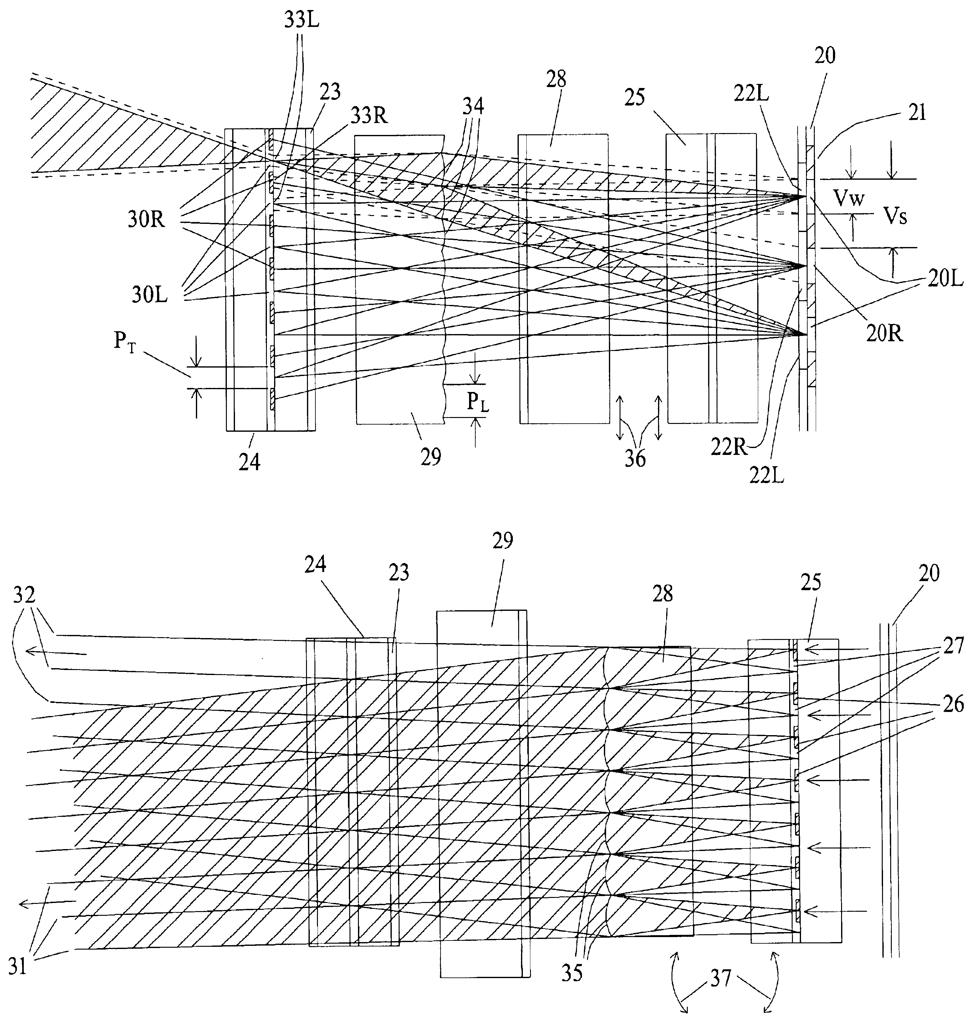
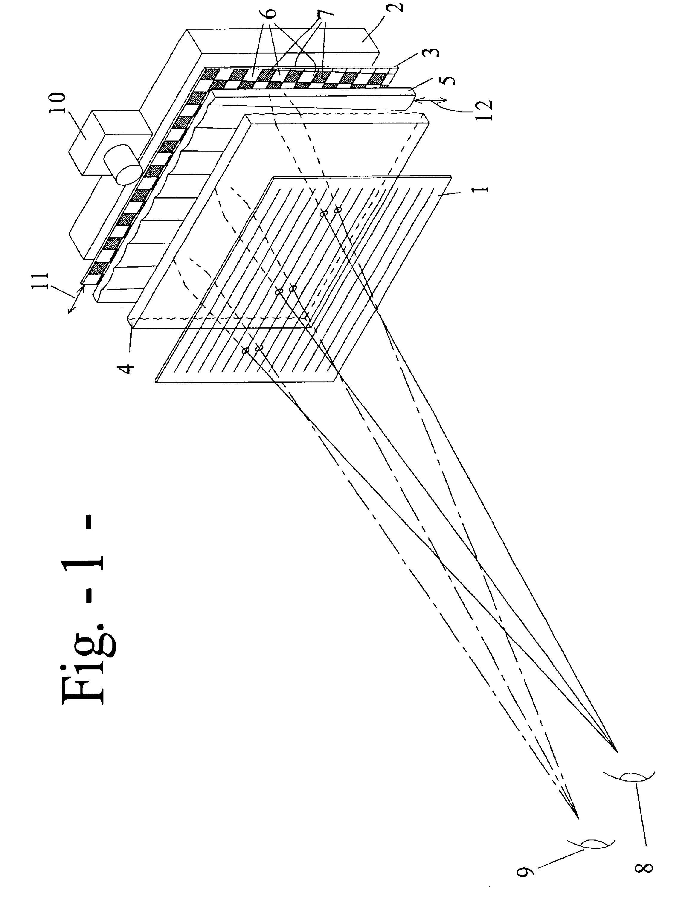
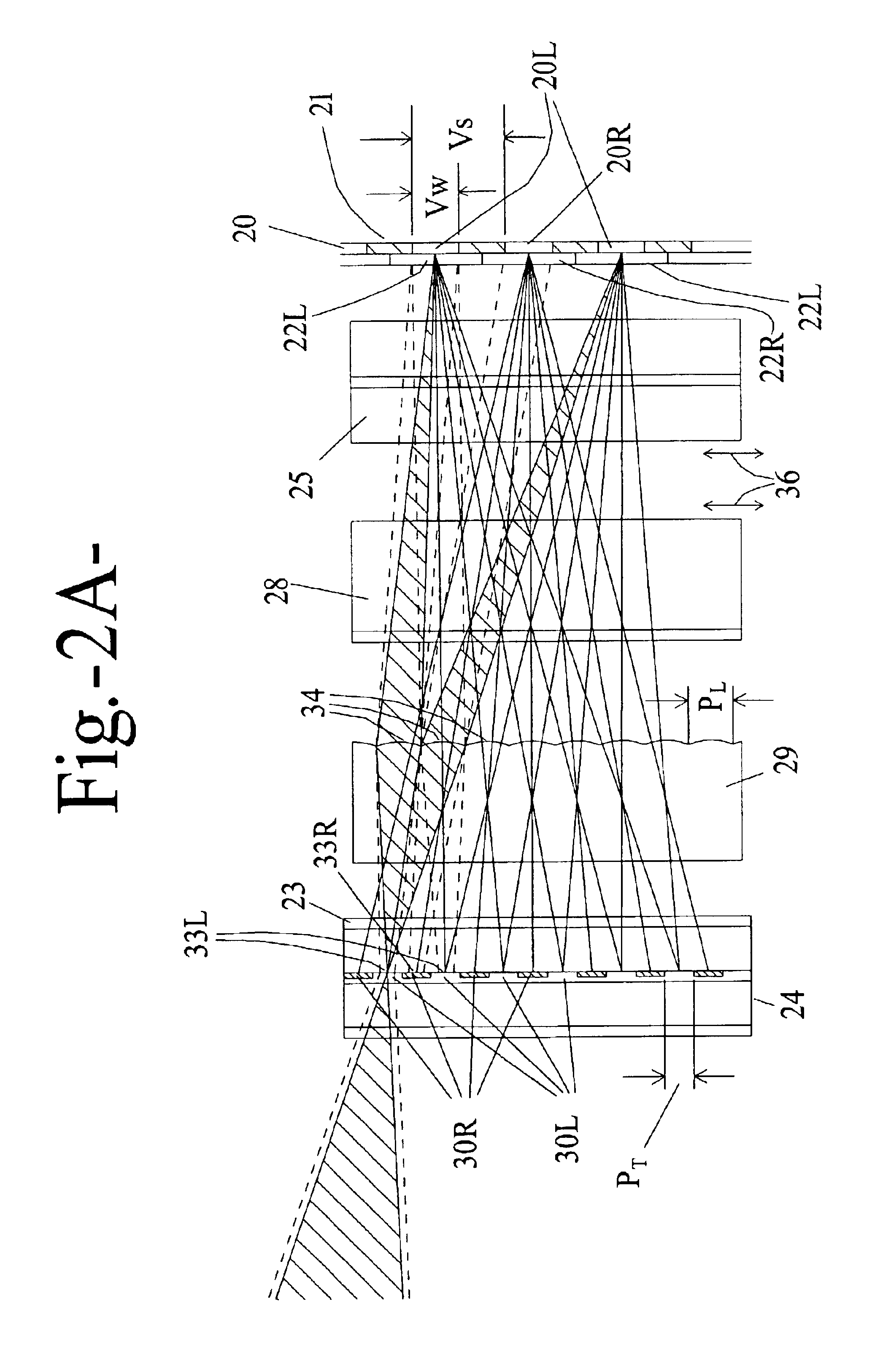
In FIG. 1, as disclosed in U.S. Pat. No. 5,936,774 (Street), an LCD 1 is positioned in front of a back light, in the form of a light box 2. The structuring of the light from box 2, before it reaches LCD 1, is achieved by a light concentration process utilising the combination of a vertically convergent array of lens elements 4 and a horizontally convergent array of lens elements 5, positioned in front of a chequered mask 3. Points at the plane of mask 3 are substantially imaged onto the plane of LCD 1, in a vertical pl...


PUM

PropertyMeasurementUnit
concentrationsaaaaaaaaaa
distanceaaaaaaaaaa
vertical widthaaaaaaaaaa

Abstract

Apparatus and method for the display of autostereoscopic images, in which two or more perspective views are generated by a single transmissive display screen is provided. A structured light source behind the screen directs light through different sets of display elements to correspondingly different viewing zones. The structured light source includes two crossed arrays of cylindrical convergent optical elements, two linear arrays of polarisation altering elements which, in conjunction with the convergent arrays and the first polariser of the LCD, prevent light from passing through a particular set of display elements and reaching the wrong viewing zone. In some variations, one or both of the polarisation altering arrays may be programmed. Observer co-ordinate data permits the correct viewing zone to be co-located with each of the observer's corresponding eyes and includes devices for accommodating changes in the observer's distance from the display. The displayed image adapts to the observer's location. All or part of the display may provide conventional two-dimensional images at the screen's full resolution.

Description

BACKGROUND OF INVENTION1. Field of the InventionThis invention relates to the field of structured light and specifically to the provision of a structured light source for use in providing stereoscopic images which require no special eye wear to be worn by the observer. Such images are usually described as autostereoscopic.2. Description of Related ArtIn U.S. Pat. No. 5,936,774 (Street), which is incorporated by reference herein, a single LCD screen provides both images for an autostereoscopic image pair. This is made possible by a structured light source. The light source is structured by the incorporation of two lenticular screens, each with its cylindrical lens elements running substantially orthogonal to those of the other, in combination with a single, patterned, typically chequered, mask and a standard back light. This arrangement causes at least a particular spectral range of the light from alternate rows of elements within the array of picture elements comprising the LCD imag...

Claims


Application Information

Patent Timeline
Patent Type & Authority Patents(United States)
IPC IPC(8): G02B27/22H04N13/00G02B30/25G02B30/27G02F1/1335G02F1/13G02F1/13357H04N13/04
CPCG02B27/2214H04N13/0418H04N13/0497H04N13/0475H04N13/0477H04N13/0285H04N13/0404H04N13/0409H04N13/0456H04N13/047H04N13/0422H04N13/305H04N13/32H04N13/376H04N13/324H04N13/368H04N13/31H04N13/286H04N13/373H04N13/361H04N13/398G02B30/27
Inventor STREET, GRAHAM STEWART BRANDON
Owner STREET GRAHAM STEWART BRANDON
Learn More