
Communication system and methodology for sending a designator for at least one of a set of time-division multiplexed channels forwarded across a locally synchronized bus

a communication system and designator technology, applied in the field of communication systems, can solve problems such as periodic blanks, jitter of the receiver, echo, etc., and achieve the effect of quickly decoding and easy decoding

Active Publication Date: 2005-03-29
MICROCHIP TECH INC
View PDF11 Cites 41 Cited by
  • Summary
  • Abstract
  • Description
  • Claims
  • Application Information

AI Technical Summary

Benefits of technology

The sync signal and command signal sent on a single signal line are preferably bytes which can be easily decoded separate from one another such that even if the sync byte is sent immediately preceding a command byte, the code of the sync byte is quickly decoded separate and apart from the command byte. Advantageously, the sync byte can be a hexadecimal FF code and the command byte can be a 0XXX XXXX binary code (or a 0X hex code). The command byte is, therefore, any byte on the signal line having an MSB of 0. The MSB of 0 guarantees that the unique pattern of eight 1s followed by one 0 occurs only during a sync. Thus, each sync byte can be quickly decoded to signify the beginning of a frame whenever eight logic 1 values are followed by a logic 0 voltage value.

Problems solved by technology

A loss in the temporal relationship can cause a receiver to present jitter, echo or, in the worst instance, periodic blanks in a voice or video stream.

Method used


Image

  • Communication system and methodology for sending a designator for at least one of a set of time-division multiplexed channels forwarded across a locally synchronized bus
  • Communication system and methodology for sending a designator for at least one of a set of time-division multiplexed channels forwarded across a locally synchronized bus
  • Communication system and methodology for sending a designator for at least one of a set of time-division multiplexed channels forwarded across a locally synchronized bus

Examples


Embodiment Construction

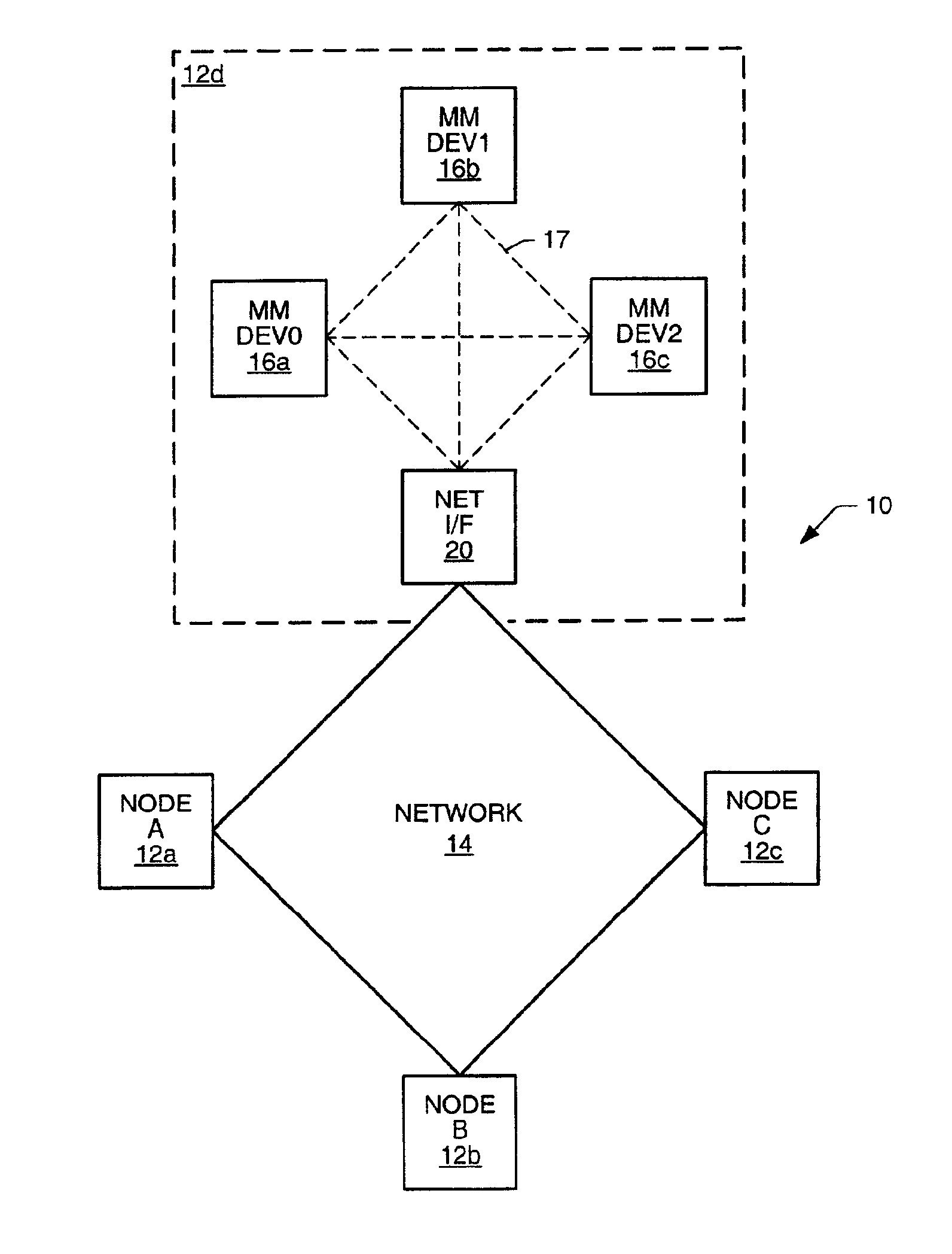
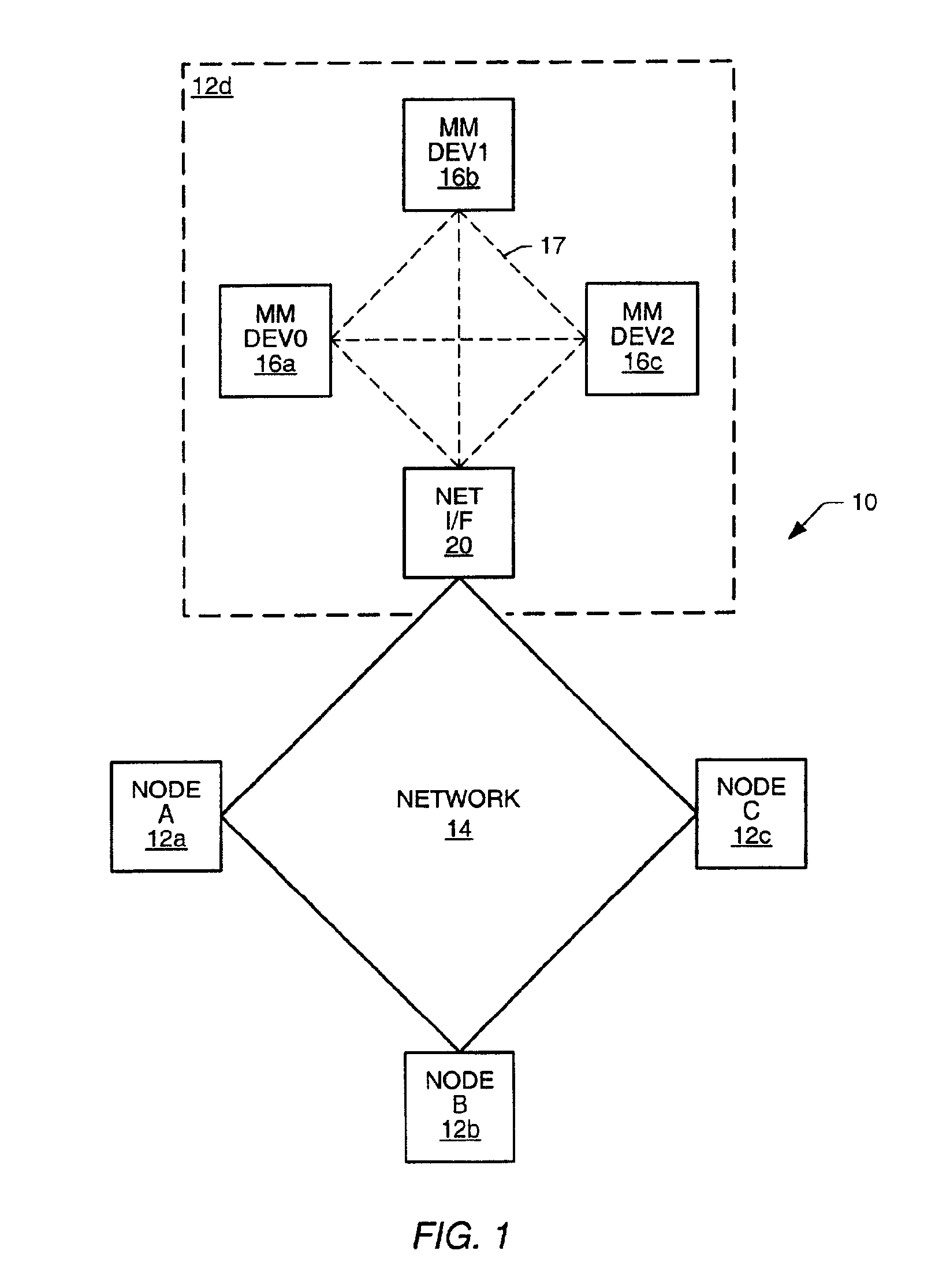
Turning now to the drawings, FIG. 1 illustrates one example of a communication system 10. Communication system 10 includes an interconnected plurality of nodes 12. For sake of brevity, only four nodes are shown. However, it is understood that system 10 can include more than four nodes and can also include multiple interconnected networks. The network shown in FIG. 1 is a ring or loop. However, it is also understood that the network backbone can be bus, star, or any other topology available to a network. Coupled between nodes 12 are corresponding transmission links 14. Transmission links14 can be optical, acoustic, or electrical (wired or wireless).

Each node 12 is preferably localized to a particular area. Within each node is at least one multimedia device. As shown in node 12d, a node can have more than one multimedia device 16. A local transmission line or local bus is shown connected between multimedia devices 16 in either a loop or bus topology as shown by the alternative phantom...


PUM


Abstract

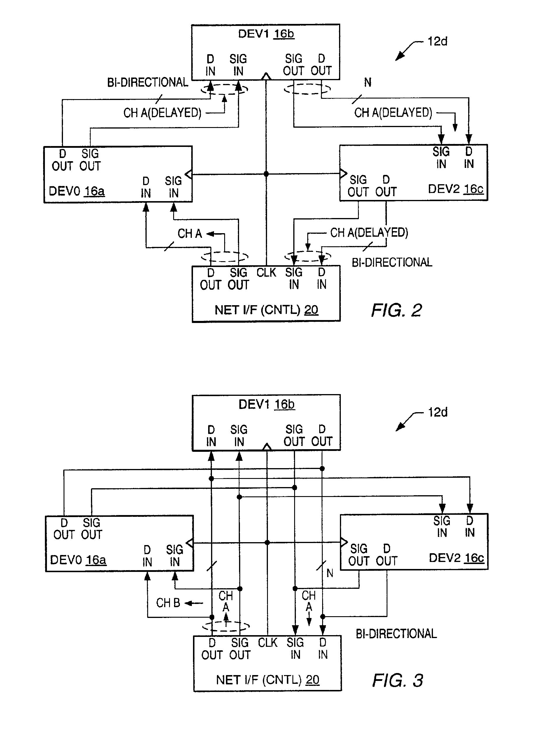
A communication system, network interface and communication port is provided that includes a media local bus. The local bus is connected between a controller and one or more multimedia devices located within a node of the communication system. The controller periodically broadcasts sync signals to the source device, or devices, to synchronize data transmission partitioned into time slots. Each time slot represents is dedicated to a particular data type. Thus, time slot 1 can accommodate packetized data, time slot 2 can accommodate synchronous data, time slot 3 can accommodate control data, and time slot 4 can accommodate isochronous data. Various combinations and variations of those time slots can occur where fewer than four data types can be present within a frame or all four data types can be present. The local bus includes a signal line and one or more data lines.

Description

BACKGROUND OF THE INVENTION1. Field of the InventionThis invention relates to a communication system, and more particularly to a bus that is time shared between a group of multimedia devices locally connected to the bus and communicable to a network coupled to the local bus by a network interface unit.2. Description of the Related ArtCommunication systems are generally well-known as containing at least two nodes interconnected by a transmission line. A node can function as a data source or destination. If the node is to receive and transmit data, then the node is a combination of a source and destination, and is sometimes known as a transceiver. The data source can transmit data in various forms. For example, the source can transmit in either an analog or digital domain. Typically, however, an analog signal is converted to a digital format before being transmitted across the transmission line to the destination.It is generally desirable that the transmission line accommodate not onl...

Claims


Application Information

Patent Timeline
Patent Type & Authority Patents(United States)
IPC IPC(8): G06F13/42
CPCG06F13/4286Y10S370/912
Inventor KNAPP, DAVID J.HO, HORACE C.
Owner MICROCHIP TECH INC
Learn More