
Surface mountable laminated thermistor device

a surface mountable, laminated technology, applied in the direction of resistor details, current responsive resistors, varistors, etc., can solve the problems of foils with insufficient mechanical strength, prone to wrapping deformation, and insufficient mechanical strength, so as to improve the structure strength, improve the stability of dimension, and improve the effect of processing and manufacturing

Inactive Publication Date: 2005-03-29
PROTECTRONICS TECH CORP
View PDF6 Cites 15 Cited by
  • Summary
  • Abstract
  • Description
  • Claims
  • Application Information

AI Technical Summary

Benefits of technology

Another goal of the present invention is to provide a surface mountable laminated thermistor device with better structure strength, so that processing and fabricating the device becomes simpler, and the problem of dimension stability is reduced.
Furthermore, the current mature fabrication process of the printed-circuit board may be used in manufacturing the surface mountable laminated thermistor device, so that the fabrication and processing for laminated circuit protection device are even easier.
Moreover, another goal of the present invention is to provide a new type of surface mountable laminated thermistor device, wherein the surface mountable laminated thermistor device having PTC conductive composite devices has broader application fields because the design of circuit conduction may achieve parallel connection effects.
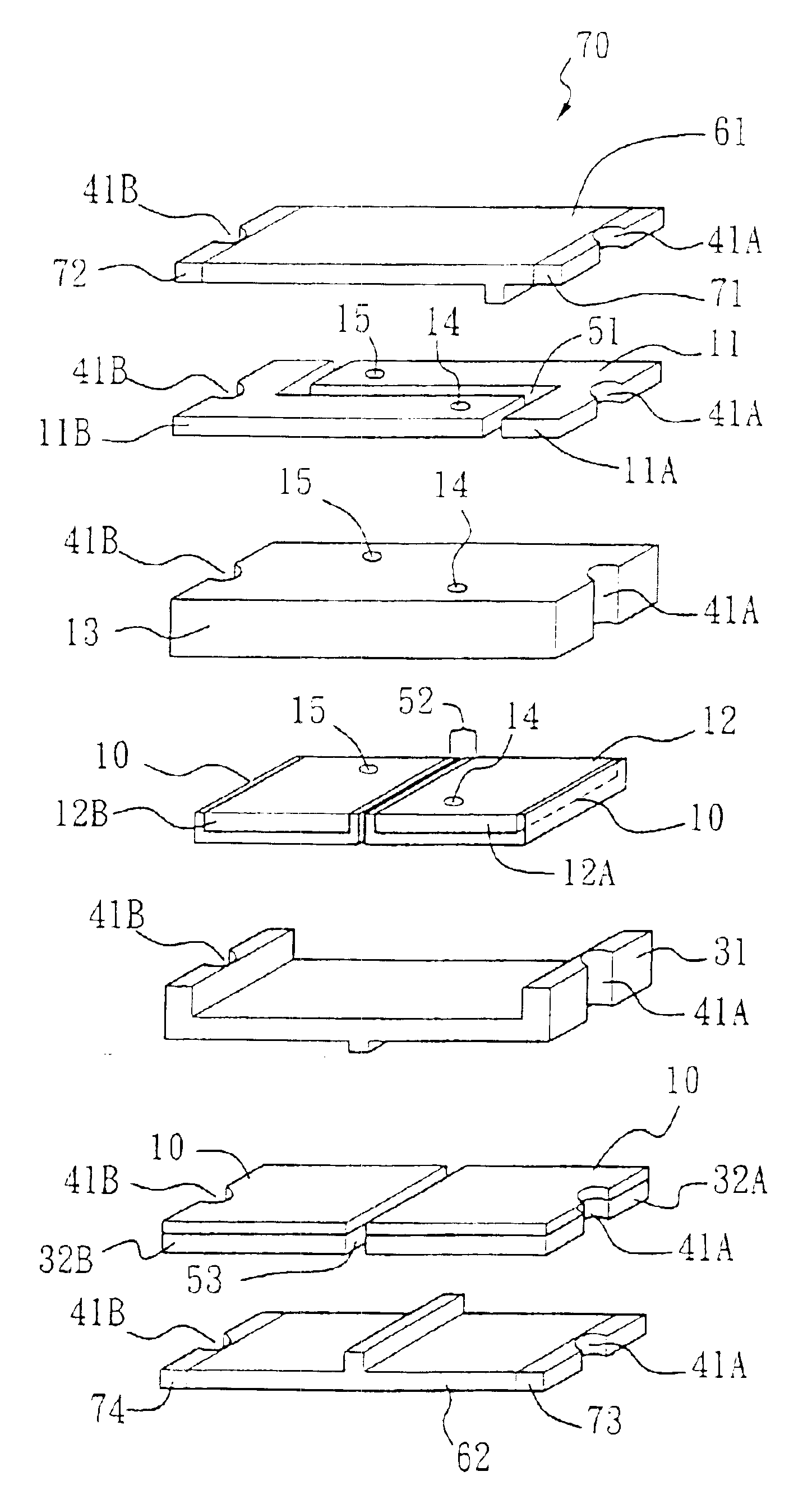
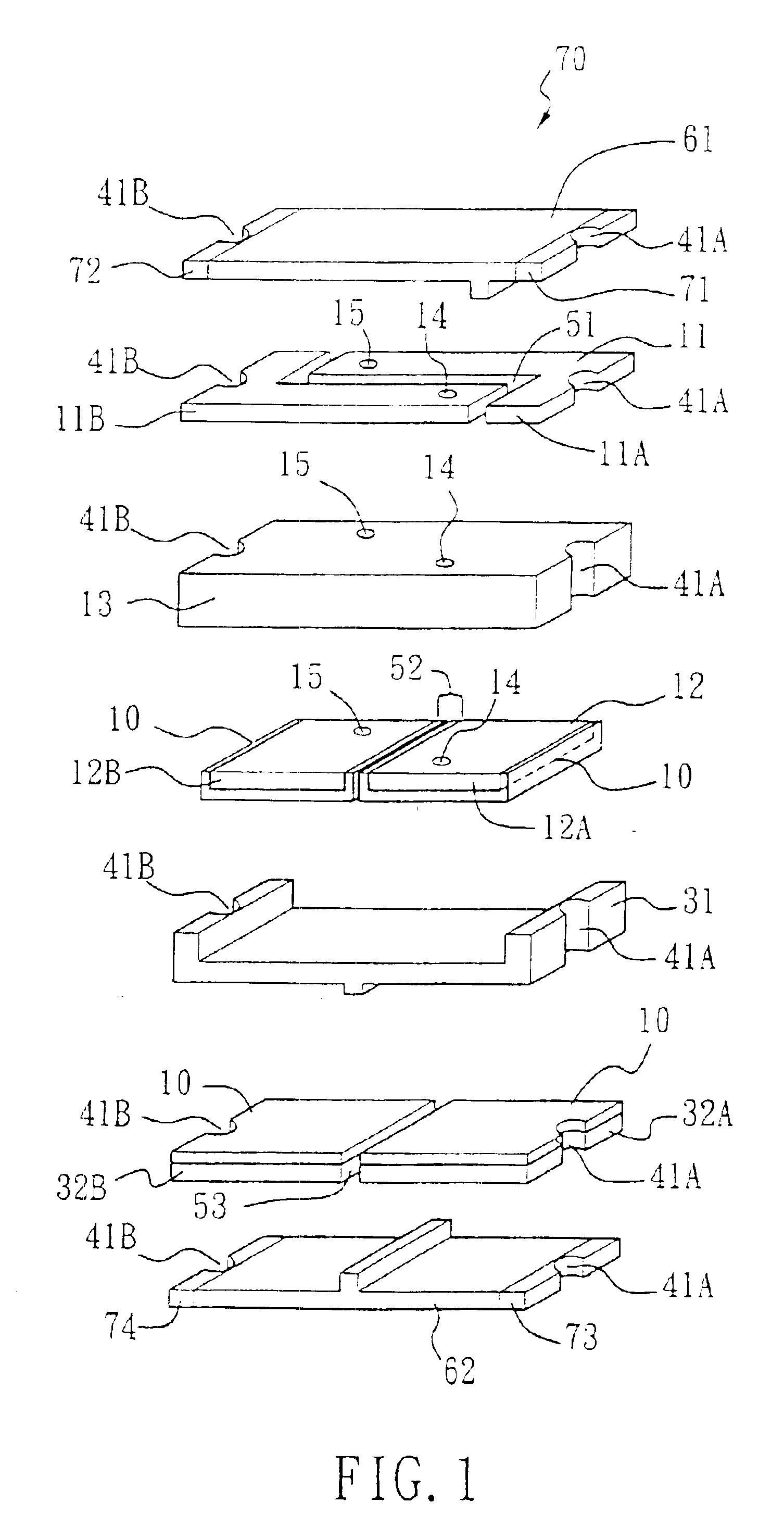
In accordance with the circuit connection design described above, there are two ways for current to flow from the first portion of first electrode to second portion of first electrode. In the first way, the current flows from the first portion of first electrode layer to first portion of second electrode layer by way of the third conductive mechanism, then flows to the first conductive part of first conductive layer by way of the PTC conductive composite layer, and finally flows to the second portion of first electrode layer by way of the first conductive mechanism. In the second way, the current flows from the first portion of first electrode layer to second portion of first electrode layer by way of the second conductive mechanism, then flows to the second portion of second electrode layer by way of the PTC conductive composite layer, and finally flows to the second portion of first electrode layer by way of the fourth conductive mechanism. Therefore, the surface mountable laminated thermistor device of the present invention obtains broader application fields because the design of circuit conduction can achieve parallel connection effects, wherein the surface mountable laminated thermistor device has PTC conductive composite devices.
Furthermore, the connected first electrode layer, insulation layer, and first conductive layer are replaced by double-sided metal foil so that the existing mature printed circuit board processing can be used. Therefore, processing and manufacturing of the surface mountable laminated thermistor device become simpler and easier.
In addition, the insulation layer of the double-sided metal foil is an insulation-reinforced layer, which may have better structure strength and better dimension stability.

Problems solved by technology

High temperature is needed in fabricating ceramics and the temperature used in the fabrication process is usually higher than 900 degrees Celsius, which complicates the process and consumes large amount of energy.
First of all, the metal foils, the conductive composite material component with PTC characteristics, and the PTC laminated structure formed by thermal laminating metal foils have insufficient mechanical strength, and are prone to wrapping to deform during the above processes.
After circuits are made, thermal laminating of other PTC laminated structures, the insulation reinforcement material or the metal electrode to form multiple-layer PTC laminated structure will cause the problem of how to align top and bottom layers accurately.
On the other hand, the technologies described above when use the metal foil and conductive composite material with the PTC characteristics are processed, because of the material is flexible so the shortcomings of possible wrapping during the processing, deformation, poor dimension stability, and uneasy processing are more likely to occur.

Method used


Image

  • Surface mountable laminated thermistor device
  • Surface mountable laminated thermistor device
  • Surface mountable laminated thermistor device

Examples


first embodiment

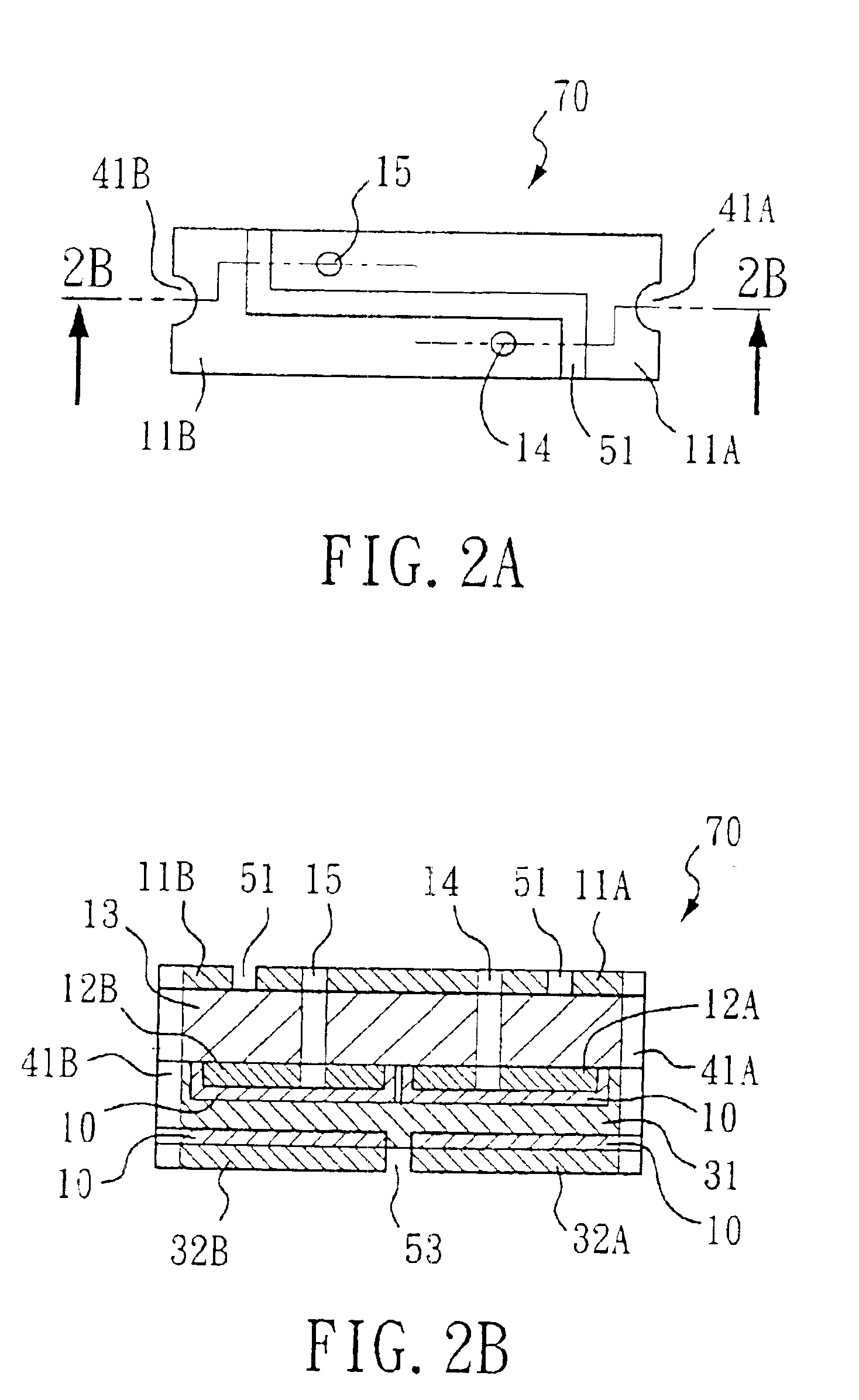
Please refer to FIGS. 1 and 2. the present invention discloses a surface mountable laminated thermistor device 70 which comprises a first electrode layer 11, a first insulation layer 13, a first conductive layer 12, a PTC conductive composite layer 31, a second electrode layer 32, a second insulation layer 61, a third insulation layer 62, a first conductive mechanism 15, a second conductive mechanism 14, a third conductive mechanism 41B, and a fourth conductive mechanism 41A. First electrode layer 11 comprises a first portion 11B and a second portion 11A, and a first isolation trench 51 is interposed between first portion 11B and second portion 11A so that it is insulated between first portion 11B and second portion 11A. Insulating materials can be filled in the first isolation trench 51 to consolidate device and ensure insulation. A second insulation layer 61 is disposed above first electrode layer 11, and a first insulation layer 13 is disposed under first electrode layer 11.

A fir...

second embodiment

Please refer to FIG. 5 and FIG. 6, which refer to the present invention that utilizes and combines two devices of the previous embodiment where the original first electrode layer is oriented inside. FIG. 6 discloses break down details of the device. This embodiment can further produce parallel effect on surface mountable laminated thermistor device.

According to the previous embodiments, the present invention provides a new type of surface mountable laminated thermistor device whose structure is different from the surface mountable laminated thermistor device of the prior art so that it achieves different electrical characteristics. And in accordance with those embodiments, current flowing from first portion 11B of first electrode 11 to second portion 11A of first electrode 11 may flow through two paths: In the first path, the current may flow from the first portion 11B of first electrode layer 11 to the first portion 32B of second electrode layer 32 by way of the third conductive me...


PUM

PropertyMeasurementUnit
thicknessaaaaaaaaaa
thicknessaaaaaaaaaa
insulatingaaaaaaaaaa

Abstract

The present invention discloses a surface mountable laminated thermistor device which utilizes current-used double sided metal foil clad substrate as a base material and a PTC conductive composite that complies with circuit connection design combinations among electrodes to obtain a surface mountable laminated thermistor device with a parallel manner, and vastly simplify the fabrication process of the surface mountable laminated thermistor device.

Description

BACKGROUND OF THE INVENTIONThe present invention relates to a surface mountable laminated thermistor device, specifically to a surface mountable laminated thermistor device having a Positive Temperature Coefficient (hereafter referred as PTC) characteristic.PTC device has been widely applied in the fields of temperature detection, safety control, temperature compensation, etc. In the past, thermistor device was primarily made from ceramics. High temperature is needed in fabricating ceramics and the temperature used in the fabrication process is usually higher than 900 degrees Celsius, which complicates the process and consumes large amount of energy. Polymeric thermistor device was then developed. Since the fabrication temperature for a surface mountable laminated thermistor device with polymer-based material is lower than 300 degree Celsius, it can be understood that the process and formation becomes easier because energy consumption is lesser, fabrication process is simpler and th...

Claims


Application Information

Patent Timeline
Patent Type & Authority Patents(United States)
IPC IPC(8): H01C7/02H01C1/14
CPCH01C7/02H01C1/1406
Inventor HUANG, CHIEN-SHANHWANG, REN-HAURCHANG, CHIH-YI
Owner PROTECTRONICS TECH CORP
Learn More