
Defibrillator with a reconfigurable battery module

a battery module and defibrillator technology, applied in the direction of electrochemical generators, parallel/serial switching, secondary cell servicing/maintenance, etc., can solve the problems of significant difficulties, design constraints, and disadvantages of prior ar

Inactive Publication Date: 2005-03-29
PHYSIO CONTROL INC
View PDF11 Cites 50 Cited by
  • Summary
  • Abstract
  • Description
  • Claims
  • Application Information

AI Technical Summary

Benefits of technology

The patent describes a way to make portable medical devices, like defibrillators, that can be charged from different voltages and can have their cells reconfigured to change the way they work. This allows for flexibility and customization in the device's charging and operating voltages.

Problems solved by technology

The prior art suffers from a number of disadvantages and limitations.
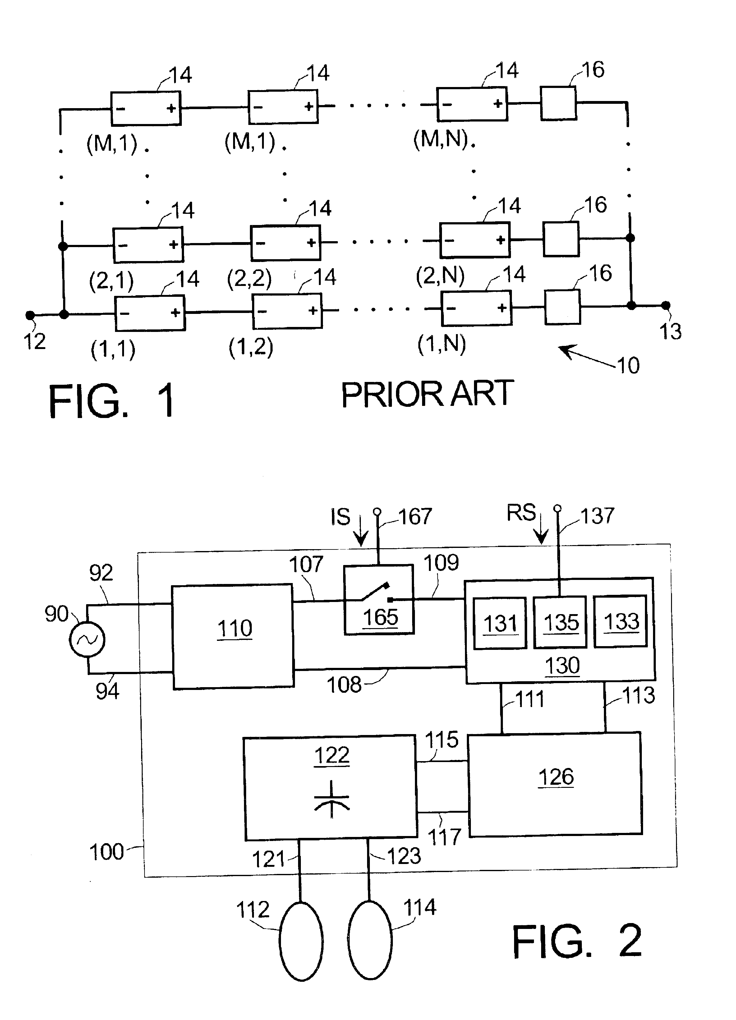
This creates design constraints, especially when it is desired to minimize degradation or failure of the module due to failure of one or more of individual cells 14.
Another limitation of the prior art is that the input voltage needed to charge the battery array must generally be equal or greater than the output or operating voltage of the battery array.
This creates significant difficulties when the application requires large outdoor or operating voltages.

Method used


Image

  • Defibrillator with a reconfigurable battery module
  • Defibrillator with a reconfigurable battery module
  • Defibrillator with a reconfigurable battery module

Examples


Embodiment Construction

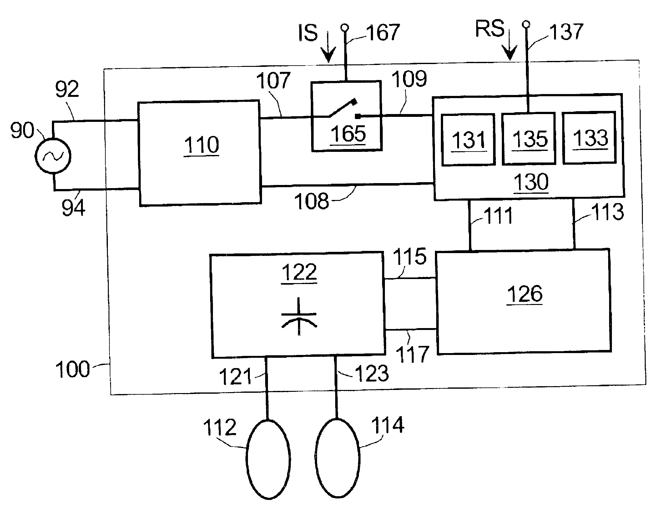
hematic electrical circuit of a portion of a defibrillator according to the present invention, showing further details;

[0018]FIG. 6A shows a simplified schematic electrical circuit of a rechargeable battery module portion of a defibrillator, according to a further embodiment of the present invention and in an unconfigured state;

[0019]FIG. 6B shows the circuit of FIG. 6A when configured for being charged;

[0020]FIG. 6C shows the circuit of FIG. 6A when reconfigured for providing an output to a further charging circuit; and

[0021]FIG. 7 is a flowchart illustrating a method for providing a rechargeable medical device according to the present invention.

DETAILED DESCRIPTION

[0022]The following detailed description is merely exemplary in nature, and is not intended to limit the invention or the application and uses of the invention. Furthermore, there is no intention to be bound by any expressed or implied theory presented in the preceding technical field, background, brief summary or the fo...


PUM

PropertyMeasurementUnit
voltageaaaaaaaaaa
polarityaaaaaaaaaa
operating voltagesaaaaaaaaaa

Abstract

Methods and apparatus are provided for portable medical devices such as defibrillators having different charging and operating voltages. The apparatus comprises a connection for receiving DC input voltage VIN, an energy storage device (e.g., a capacitor), a battery having at least two cells therein coupled to the connection and the capacitor, and switches to selectively reconfigure the battery cells so as to: (i) charge from VIN, and (ii) discharge to the capacitor at VOUT>VIN. The method comprises charging the battery from VIN while its cells are arranged substantially in parallel, then reconfiguring the switches to arrange some of the charged cells substantially in series to give VOUT>VIN, and then charging the capacitor therefrom. The cells are thereafter reconfigured back to the parallel arrangement ready to be recharged from VIN. Isolation switches are conveniently provided to isolate the battery from VIN while charging the capacitor.

Description

CROSS-REFERENCES TO RELATED APPLICATIONS[0002]This application claims the benefit of U.S. Provisional Application No. 60 / 409,948, filed Sep. 11, 2002.[0003]Commonly assigned U.S. patent application Ser. No. 10 / 035,297 filed Oct. 26, 2001 may be found to be related.TECHNICAL FIELD OF THE INVENTION[0004]The present invention generally relates to battery power sources for portable medical equipment, and more particularly to power sources for medical devices such as defibrillators and other equipment having different charging and operating voltages.BACKGROUND OF THE INVENTION[0005]Battery operated devices find diverse applications ranging from small and simple children's toys to sophisticated laptop computers and large electric powered vehicles. Batteries are also used in medical devices, such as manual, automatic or semiautomatic defibrillators. Defibrillators and other medical devices may be external or implanted in the body. Automatic and semiautomatic external defibrillators are ref...

Claims


Application Information

Patent Timeline
Patent Type & Authority Patents(United States)
IPC IPC(8): H01M10/46H01M10/42H02J7/00H01M10/44H02J7/34
CPCH02J7/345H02J7/0024
Inventor KAVOUNAS, GREGORY T.
Owner PHYSIO CONTROL INC
Learn More