
High pressure fuel accumulation device

a fuel accumulation device and high-pressure technology, which is applied in the direction of liquid fuel feeders, machines/engines, mechanical equipment, etc., can solve the problems of troublesome mass-producing plural models of the common, high fabrication cost, and standardization of the common fabrication. , to achieve the effect of reducing the fluctuation of the injection amount, reducing the pressure pulsation, and reducing the production cos

Inactive Publication Date: 2005-03-29
DENSO CORP
View PDF8 Cites 8 Cited by
  • Summary
  • Abstract
  • Description
  • Claims
  • Application Information

AI Technical Summary

Benefits of technology

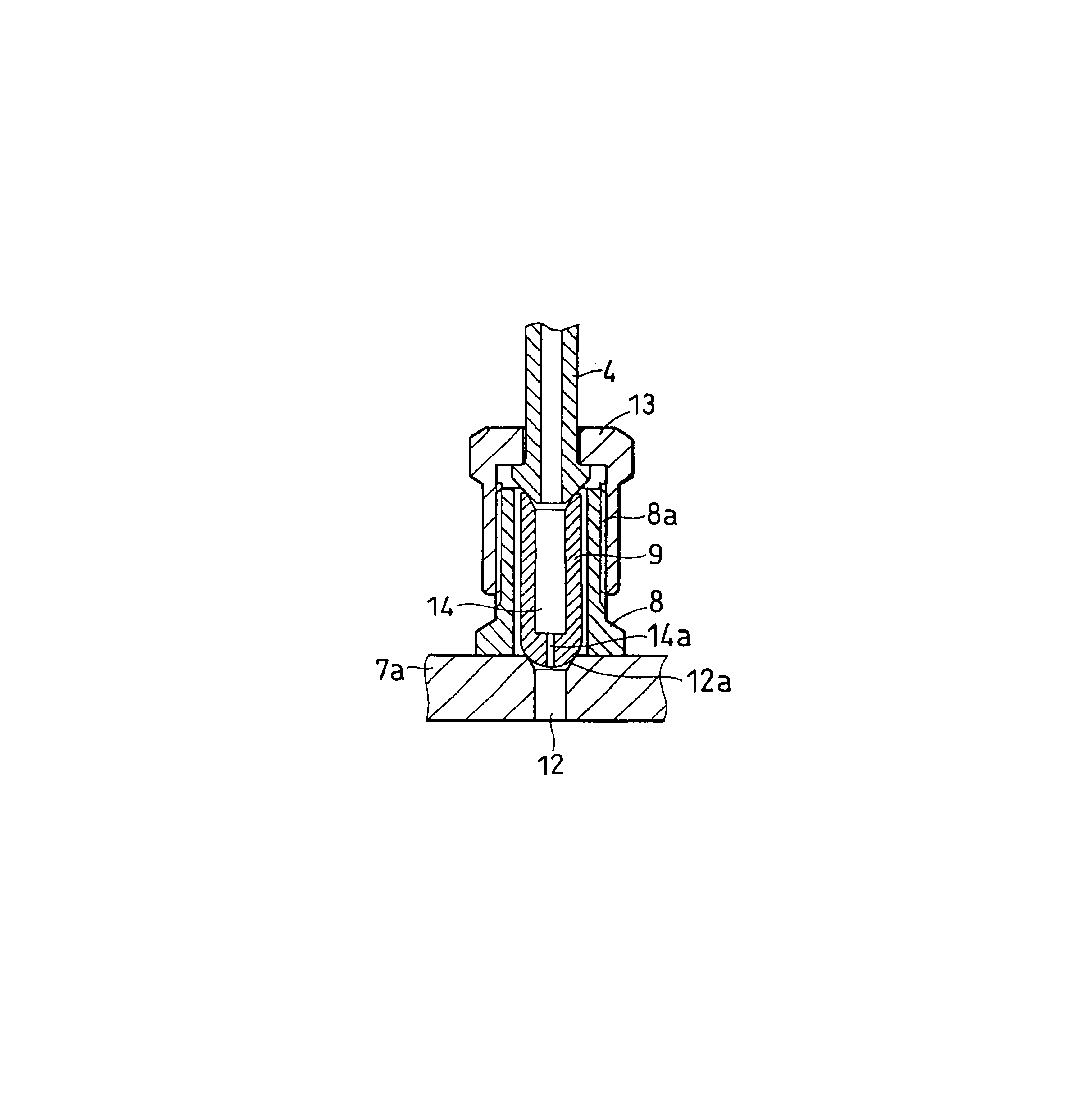
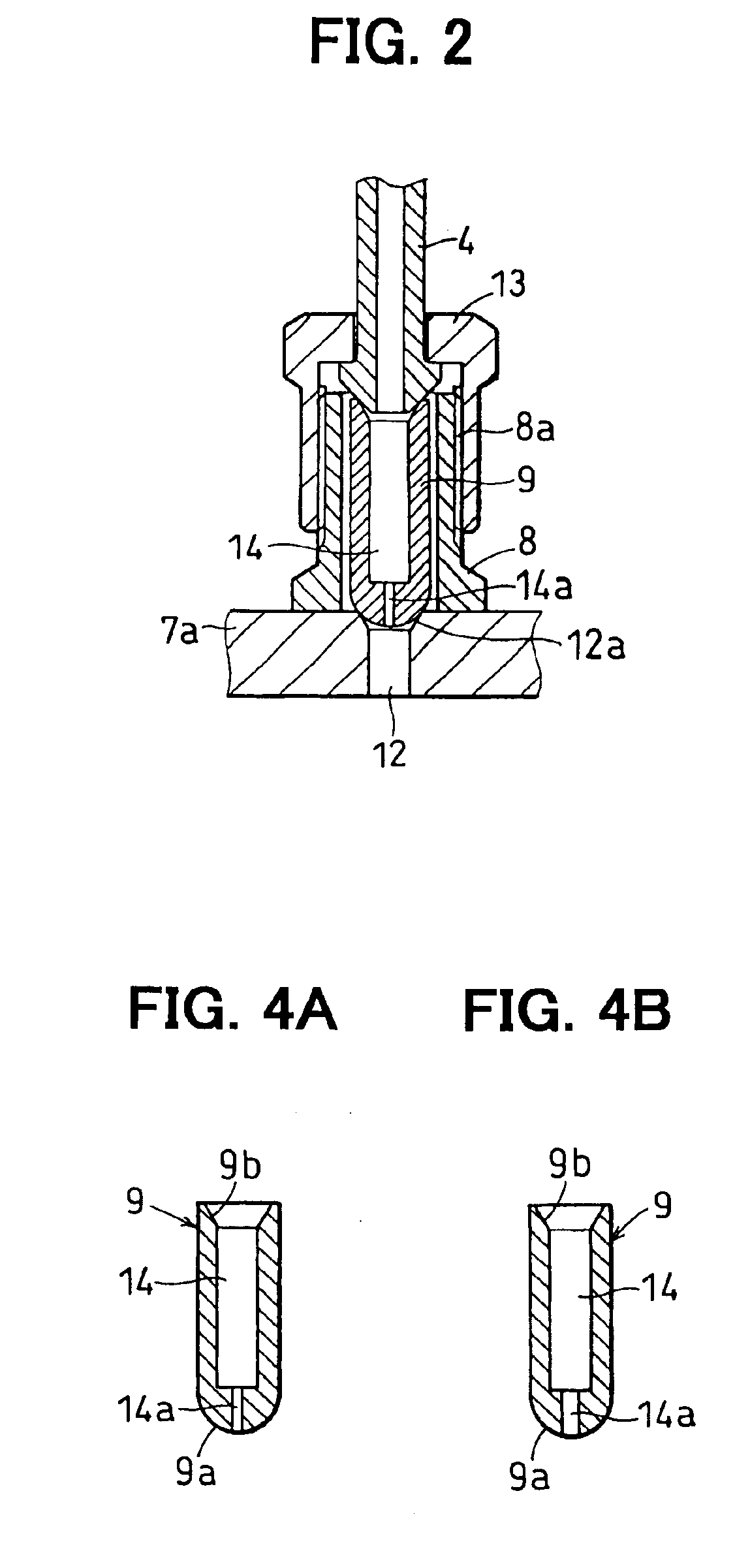
The present invention provides a high pressure fuel accumulation device with a throttle that can be easily formed at a lower manufacturing cost. The device includes a main body with an accumulation chamber for accumulating high pressure fuel, a through-hole radially extending from the accumulation chamber, and a hollowed pipe joint to which a fuel distribution pipe is fastened. A cylindrical intermediate member is housed inside the hollowed pipe joint and sandwiched under pressure between the fuel distribution pipe and the exterior circumferential wall of the main body. The cylindrical intermediate member has a conduit with an orifice, which is easily and accurately manufactured at a lower cost compared to conventional accumulation pipes. The accumulation pipe and the pipe joint are separately formed, resulting in lower manufacturing cost and standardization of the installation position. The orifice is formed at an axial end of the conduit, and the main body has plural pieces of the through-holes formed in the circumferential wall thereof at a given longitudinal spacing, which serves as a fuel outlet of the main body to be connected with each injector via the fuel delivery pipe. This construction reduces pressure pulsation generated by fuel injection of an injector and stabilizes fuel pressure in the accumulation chamber, resulting in less fluctuation of injection amount and injection timing of the other injector.

Problems solved by technology

The conventional accumulation type fuel injection system has a drawback in that, since pressure of the fuel accumulated in the common rail is extremely high (for example, about 150 Mpa), if pressure pulsation occurs on injecting the fuel from one of the injectors, the pressure pulsation is likely to cause pressure variation in the common rail so that respective fuel injection amount and injection timing of the other injectors are fluctuated.
According to a structure shown in FIG. 8, since the throttle 120 is positioned at a bottom of the pipe joint 110 to which a high pressure pipe 130 is connected, fabrication of the throttle 120 is a troublesome work and it is rather difficult to form the throttle 120 with accurate dimension, resulting in higher fabrication cost.
Further, since the throttle 120 is formed directly in a main body of the common rail 100, it is troublesome to mass-produce plural models of the common rails 100 in which respective models thereof have substantially uniform main bodies but have different diameters of the throttles.
That is, it is very difficult to standardize fabrication of the common rail 100, resulting in higher manufacturing cost of the high pressure fuel accumulation device.

Method used


Image

  • High pressure fuel accumulation device
  • High pressure fuel accumulation device
  • High pressure fuel accumulation device

Examples


first embodiment

(First Embodiment)

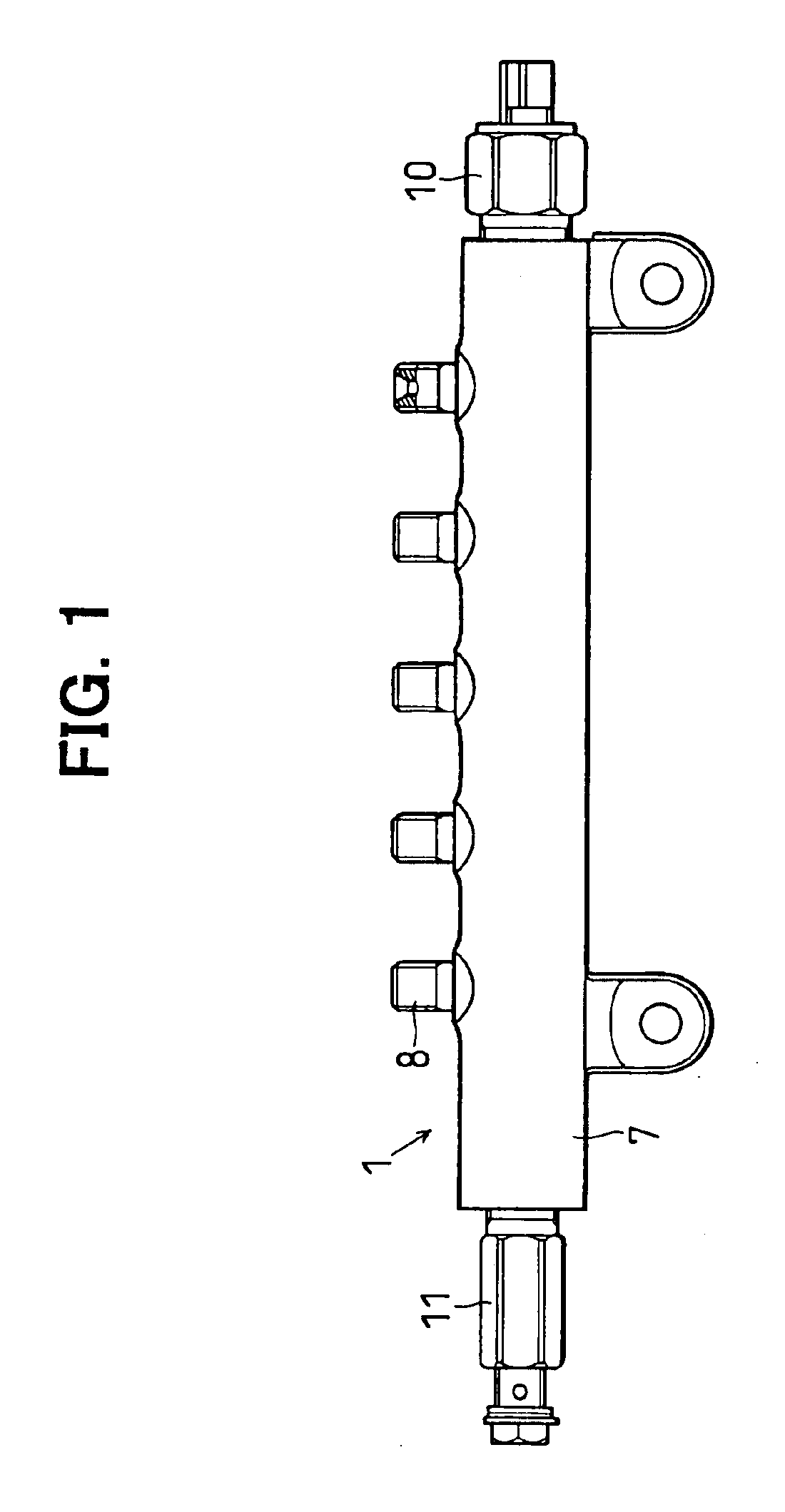
A high pressure fuel accumulation device according to a first embodiment, which is applied to a accumulation type fuel injection system for 4 cylinder diesel engine, is described with FIGS. 1 to 5.

As shown in FIG. 3, the accumulation type fuel injection system has a common rail 1, a high pressure pump 3 for sucking fuel from a fuel tank 2, pressurizing and discharging the pressurized fuel to the common rail 1, injectors 5 for injecting into respective cylinders of the diesel engine the high pressure fuel supplied via respective high pressure pipes (fuel distribution pipes) 4 from the common rail and ECU (electrical control unit) 6 for controlling the system itself. The common rail 1 and the high pressure pipe 4 constitute a high pressure fuel accumulation device.

As shown in FIG. 2, the common rail 1 is composed of an accumulation pipe (main body) 7 in which the high pressure fuel is accumulated, pipe joints 8 to each of which each of the high pressure pipes 4 is fa...

second embodiment

(Second Embodiment)

In a high pressure fuel accumulation device according to a second embodiment, the seat surface 9b of the orifice member 9 is positioned above an axial upper end of the pipe joint 8, as shown in FIG. 6.

Even if thread diameter of the pipe joint is relatively short so that an outer diameter of the orifice member is small, it is necessary to have the seat surface 9b of the orifice member 9 whose area is sufficiently large to be opposed to the seat portion of the high pressure pipe 4a. To this end, an axial end of the orifice member 9 on a side opposite to the orifice 14a is positioned above the axial upper end of the pipe joint 8 and has a flange 9c in which the seat surface 9b is formed.

With this structure, even if the thread diameter of the pipe joint 8 is smaller than that of the first embodiment, the orifice member 9 has the seat surface 9b sufficiently large to secure reliable sealing.

third embodiment

(Third Embodiment)

In a high pressure fuel accumulation device according to a third embodiment, the pipe joint 8 is formed integrally with the accumulation pipe 7 into a single piece, as shown in FIG. 7. The third embodiment, in which the orifice 14 is formed in the orifice member 9 inserted into the interior of the pipe joint 8, has the same advantage as the first embodiment. However, the third embodiment is inferior to the first embodiment in fabrication standardization of the common rail 1, since the pipe joint 8 is formed integrally with the accumulation pipe 7.


PUM


Abstract

A common rail has an accumulation pipe in which high pressure fuel is accumulated, a pipe joint to which a high pressure pipe is connected and an orifice member housed inside the pipe joint. The orifice member is provided with a conduit through which a fuel port formed in the accumulation pipe communicates with the high pressure pipe. The conduit is provided at an end thereof with an orifice. The orifice serves to reduce pressure pulsation generated by fuel injection of an injector so that fuel pressure in the common rail is stable. Since the orifice is formed in the orifice member housed in the pipe joint, the orifice is easily and accurately manufactured at a lower cost, compared to an orifice formed in the accumulation pipe. It is easy to standardize the manufacture of plural models of common rails whose orifice diameters are different.

Description

BACKGROUND OF THE INVENTION1. Field of the InventionThe present invention relates to a pipe joint structure of a high pressure fuel accumulation device applicable to an accumulation type fuel injection system.2. Description of Related ArtConventionally, an accumulation type fuel injection system is known, in which high pressure fuel is accumulated in an accumulation device so called a common rail and the high pressure fuel thus accumulated is injected from respective injectors to respective cylinders of a diesel engine. The conventional accumulation type fuel injection system has a drawback in that, since pressure of the fuel accumulated in the common rail is extremely high (for example, about 150 Mpa), if pressure pulsation occurs on injecting the fuel from one of the injectors, the pressure pulsation is likely to cause pressure variation in the common rail so that respective fuel injection amount and injection timing of the other injectors are fluctuated.To cope with this drawback...

Claims


Application Information

Patent Timeline
Patent Type & Authority Patents(United States)
IPC IPC(8): F02M55/02F02M55/00F02M63/02F02M63/00
CPCF02M55/005F02M55/025F02M2200/315F02M63/02
Inventor KONDO, JUN
Owner DENSO CORP
Learn More