
Video object tracking by estimating and subtracting background

a video object and background technology, applied in the field of digital graphics, can solve the problems of difficulty in identifying video objects or object portions with a rapidly changing shape, difficulty in tracking a human leg during a scene where the person is walking, and difficulty in tracking objects or object portions

Inactive Publication Date: 2005-03-22
UNIV OF WASHINGTON
View PDF6 Cites 83 Cited by
  • Summary
  • Abstract
  • Description
  • Claims
  • Application Information

AI Technical Summary

Benefits of technology

An advantage of the invention is that objects having rapidly changes shapes are accurately tracked against a motionless background. Information in prior and future frames is used to detect object motion. the object can change internally and even be self-occluding. Another advantage is that previously unrevealed (i.e., occluded) portions of the background are identified, improving object estimation accuracy. Another advantage is that holes in objects also are tracked accurately.
is that objects having rapidly changes shapes are accurately tracked against a motionless background. Information in prior and future frames is used to detect object motion. the object can change internally and even be self-occluding. Another advantage is that previously unrevealed (i.e., occluded) portions of the background are identified, improving object estimation accuracy. Another advantage is that holes in objects also are tracked accurately.

Problems solved by technology

One shortcoming of edge based tracking and segmentation methods is the difficulty in identifying video objects or object portions with a rapidly changing shape.
For example tracking a human leg during a scene where the person is walking is difficult because the shape of the leg is continually changing.
Difficulties also arise in tracking objects or object portions which are being occluded and disoccluded in various image frames.

Method used


Image

  • Video object tracking by estimating and subtracting background
  • Video object tracking by estimating and subtracting background
  • Video object tracking by estimating and subtracting background

Examples


Embodiment Construction

Exemplary Processing Environment

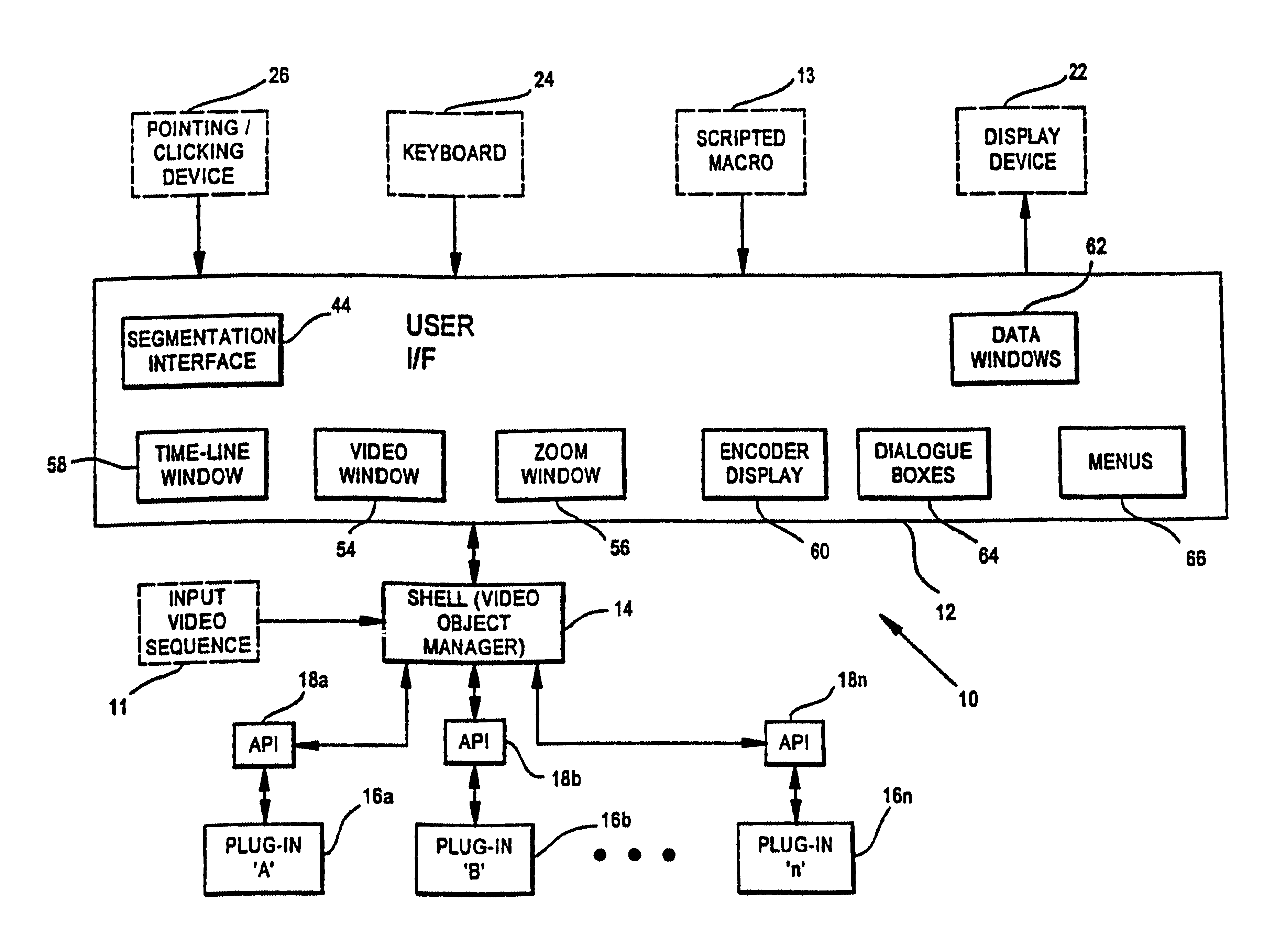
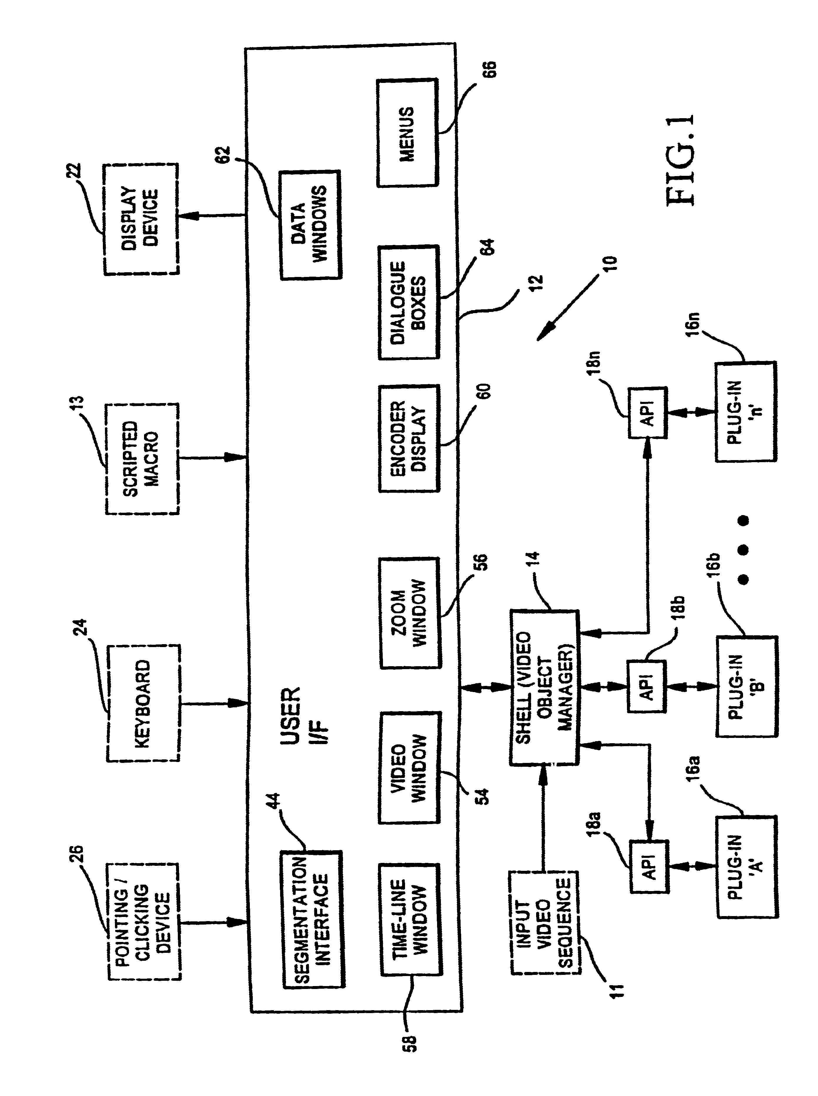
FIG. 1 shows a block diagram of an exemplary host interactive processing environment 10 for locating, tracking and encoding video objects. The processing environment 10 includes a user interface 12, a shell environment 14 and a plurality of functional software ‘plug-in’ programs 16. The user interface receives and distributes operator inputs from various input sources, such as a point and clicking device 26 (e.g., mouse, touch pad, track ball), a key entry device 24 (e.g., a keyboard), or a prerecorded scripted macro 13. The user interface 12 also controls formatting outputs to a display device 22. The shell environment 14 controls interaction between plug-ins 16 and the user interface 12. An input video sequence 11 is input to the shell environment 14. Various plug-in programs 16a-16n may process all or a portion of the video sequence 11. One benefit of the shell 14 is to insulate the plug-in programs from the various formats of potential video seque...


PUM


Abstract

An object is tracked among a plurality of image frames. In an initial frame an operator selects an object. The object is distinguished from the remaining background portion of the image to yield a background and a foreground. A model of the background is used and updated in subsequent frames. A model of the foreground is used and updated in the subsequent frames. Pixels in subsequent frames are classified as belonging to the background or the foreground. In subsequent frames, decisions are made, including: which pixels do not belong to the background; which pixels in the foreground are to be updated; which pixels in the background were observed incorrectly in the current frame; and which background pixels are being observed for the first time. In addition, mask filtering is performed to correct errors, eliminate small islands and maintain spatial and temporal coherency of a foreground mask.

Description

BACKGROUND OF THE INVENTIONThis invention relates to digital graphics, and more particularly to a method and apparatus for digital image object tracking and segmentation.In composing and manipulating digital images for providing special effects in movie and video clips and for a variety of other imaging and graphics applications, image objects are identified and tracked. In movies, for example, image objects are inserted or manipulated to alter a scene in a realistic manner. Objects or regions from still frames or photographs are inserted into a sequence of frames to create a realistic image sequence.Segmentation is a technique in which an object within an image is traced so that it may be extracted. Among the earliest segmentation methods is a manual method in which an operator manually selects points along a boundary of the object to outline the image. The points then are connected to formed a closed object. For example, straight lines have been used to connect the points. The mor...

Claims


Application Information

Patent Timeline
Patent Type & Authority Patents(United States)
IPC IPC(8): G06T5/00G06T7/20H04N5/272
CPCG06T7/0083G06T7/2053G06T7/0091G06T2207/10016G06T7/12G06T7/155G06T7/254
Inventor SCHOEPFLIN, TODDHAYNOR, DAVID R.SAHR, JOHN D.KIM, YONGMIN
Owner UNIV OF WASHINGTON
Learn More