Fitting jig of endoscope hood member
a technology of endoscope and hood member, which is applied in the field of fitting jig of endoscope hood member, can solve the problems of insufficient pressed end portion into the hood member, less effective hood member, and inability to view more inner areas of the stomach. achieve the effect of convenient and precise installation
- Summary
- Abstract
- Description
- Claims
- Application Information
AI Technical Summary
Benefits of technology
Problems solved by technology
Method used
Image

Examples
first embodiment
(First Embodiment)
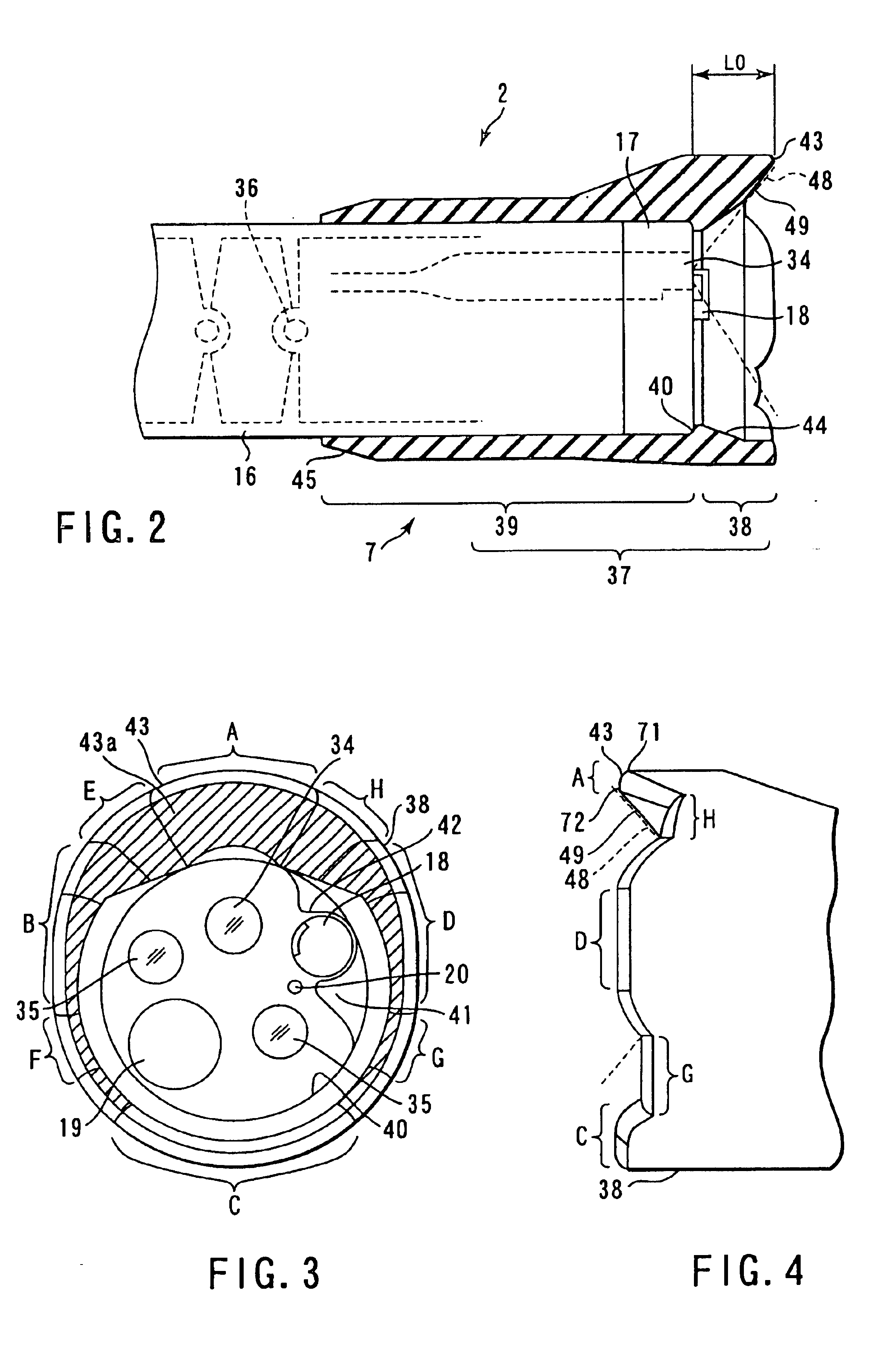
FIGS. 1 to 6 relates to a first embodiment of the present invention. FIG. 1 is a view illustrating the entire configuration of an endoscope apparatus. FIG. 2 is a sectional view of an end portion of an endoscope. FIG. 3 is a front view of the end portion of the endoscope. FIG. 4 is a side view showing a hood member removably connected to the end portion of the endoscope. FIG. 5 is a plan view showing an observed image displayed on a monitor. FIG. 6 is a view illustrating an observing view area used if the observed image in FIG. 5 is displayed.
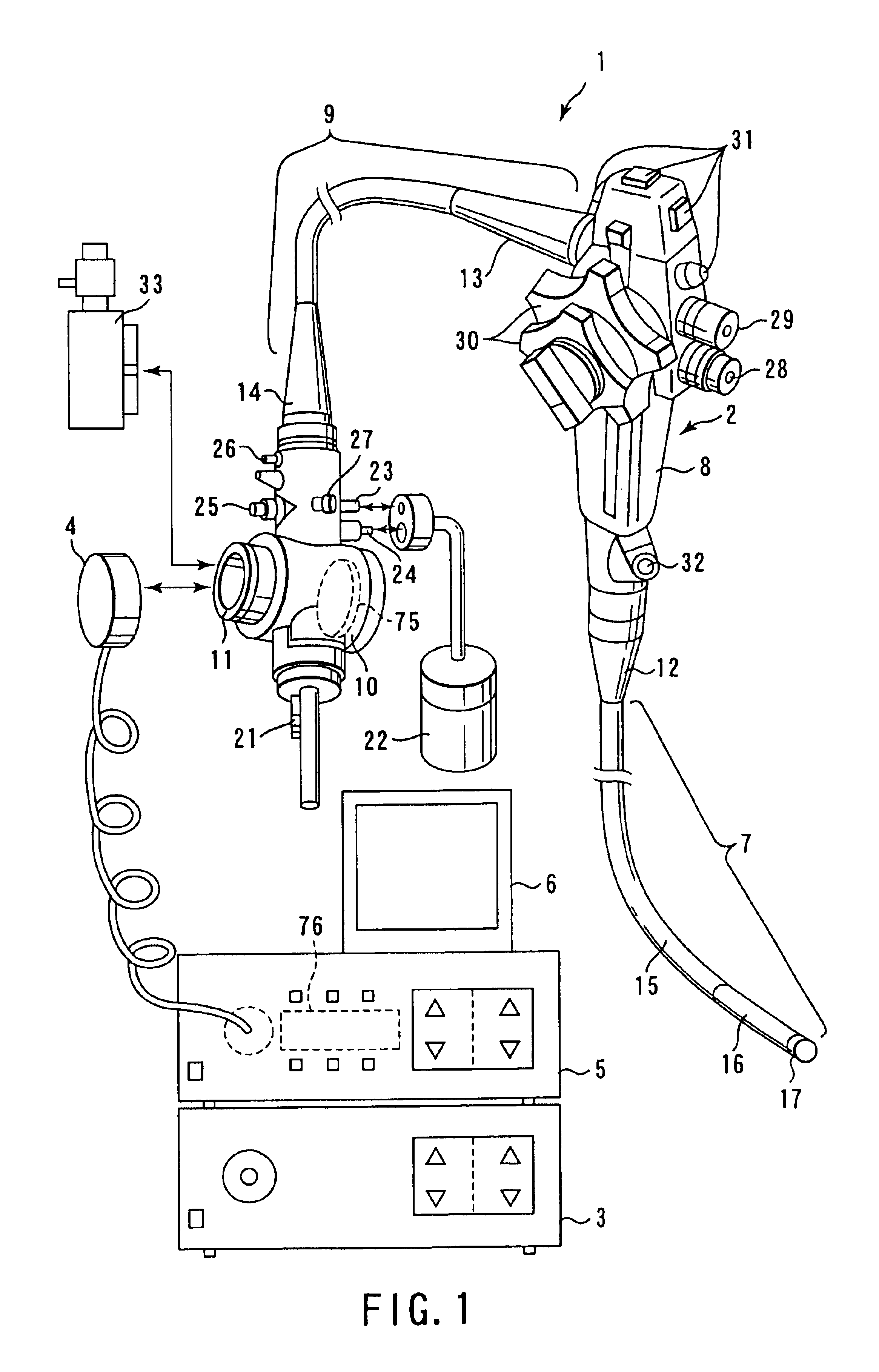
FIG. 1 shows the entire configuration of the endoscope apparatus.
As shown in FIG. 1, the endoscope apparatus 1 is composed of an endoscope 2, a light source device 3, a video processor 5, and a monitor 6.
The endoscope 2 comprises image pickup means described later. The light source device 3 is removably connected to the endoscope 2 to supply illumination light to a light guide formed in the endoscope 2. The video processor 5 i...
second embodiment
(Second Embodiment)
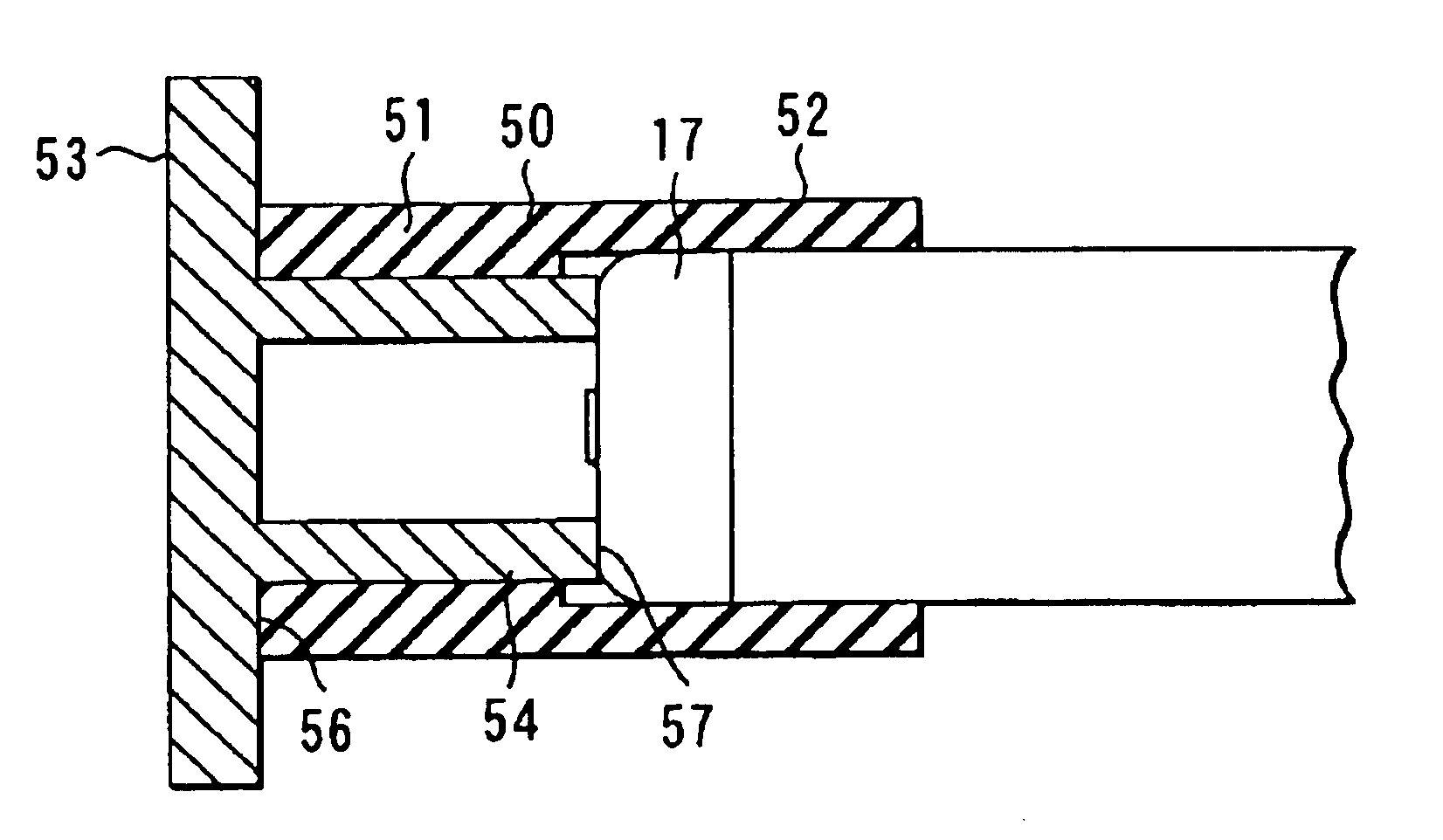
FIG. 9 is a partly cutaway side view of an end portion of an endoscope according to a second embodiment of the present invention.
The second embodiment shown in FIG. 9 differs from the first embodiment in that a hood member 137 is integrated with the end portion 17.
As shown in FIG. 9, the hood member 137 is formed of a hard resin such as polysulfon and also acts as an insulating cover that covers a metal part inside the end portion 17.
The observing optical system 34 of the end portion 17 has an observation view area 47 similar to that in the first embodiment, shown in FIG. 6.
An end edge portion 143 of the hood member 137 has slope portions 149 formed at the respective positions and corresponding to the slope 48 of the observation view area 47.
The slope portion 149 is formed in the end edge portion 143 of the hood member 137 and corresponds to the slope 48 of the observation view area 47 at the respective positions as in the case with the first embodiment, shown in ...
third embodiment
(Third Embodiment)
FIGS. 10 and 11 relate to a third embodiment of the present invention. FIG. 10 is a side view showing a protruding portion of the endoscope. FIG. 11 is a plan view showing an observed image displayed on a monitor.
As shown in FIG. 10, a protruding portion 238 of a hood member 237 provided at an end portion of the endoscope of this embodiment has a portion 243a formed so that a very small part of the end portion of the end edge portion 243 overlaps the slope 48 of the observation view area 47. That is, the portion 243a extends into the observation view area 47.
The amount of overlapping x by which the end edge portion 243 overlaps the observation view area 47 at positions distant from the center of the observation view area in the diagonal direction X shown in FIG. 6 is larger than the amount of overlapping y at other positions. That is, as shown in FIG. 11, considering aberration in the observing optical system 34, the amounts of overlapping x and y are set so that t...
PUM
 Abstract
Description
Claims
Application Information
 - R&D
- Intellectual Property
- Life Sciences
- Materials
- Tech Scout
- Unparalleled Data Quality
- Higher Quality Content
- 60% Fewer Hallucinations
Browse by: Latest US Patents, China's latest patents, Technical Efficacy Thesaurus, Application Domain, Technology Topic, Popular Technical Reports.
© 2025 PatSnap. All rights reserved.Legal|Privacy policy|Modern Slavery Act Transparency Statement|Sitemap|About US| Contact US: help@patsnap.com