
Fan blade assembly

a technology of blades and blades, applied in the direction of liquid fuel engines, marine propulsion, vessel construction, etc., can solve the problems of reducing the service life of the fan blade, so as to facilitate the accurate installation of the core shaft

Inactive Publication Date: 2009-04-16
HSU TING WEI MR
View PDF4 Cites 5 Cited by
  • Summary
  • Abstract
  • Description
  • Claims
  • Application Information

AI Technical Summary

Benefits of technology

[0007]The present invention has been accomplished under the circumstances in view. It is therefore the main object of the present invention to provide a fan blade assembly, which facilitates accurate installation of the core shaft in the fan blade body for enabling the core shaft to support magnetic levitation rotation of the fan blade body stably.

Problems solved by technology

When the mechanical operation speed of a cooling fan is increased, the noise level resulted from friction between the core shaft and the axle bearing is relatively increased.
Excessive high temperature during operation of a cooling fan may cause burnout of the component parts.
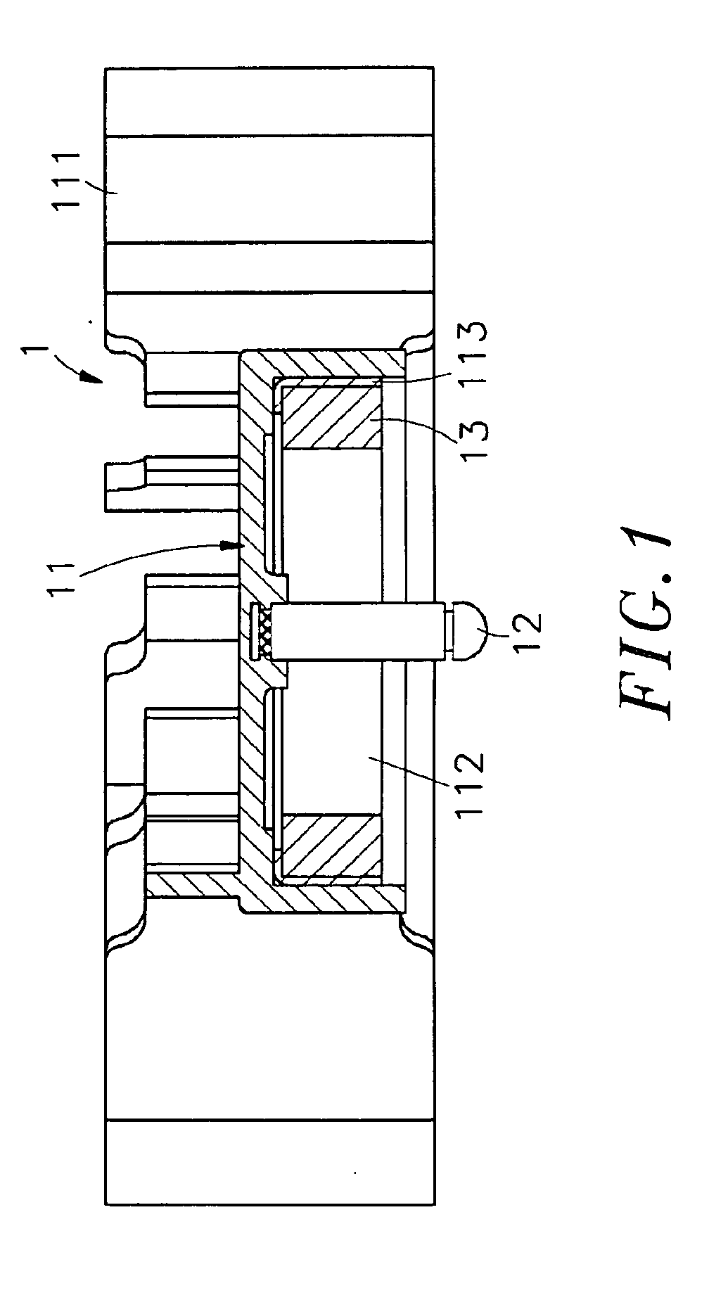
This design of magnetic levitation motor fan still has drawbacks.
A small deviation of the core shaft 12 will cause unstable rotation of the fan blade assembly 1.
The complicated installation procedure of the core shaft 12 greatly increases the consumption of labor and time during fabrication of the magnetic levitation motor fan.

Method used


Image

  • Fan blade assembly
  • Fan blade assembly
  • Fan blade assembly

Examples


Embodiment Construction

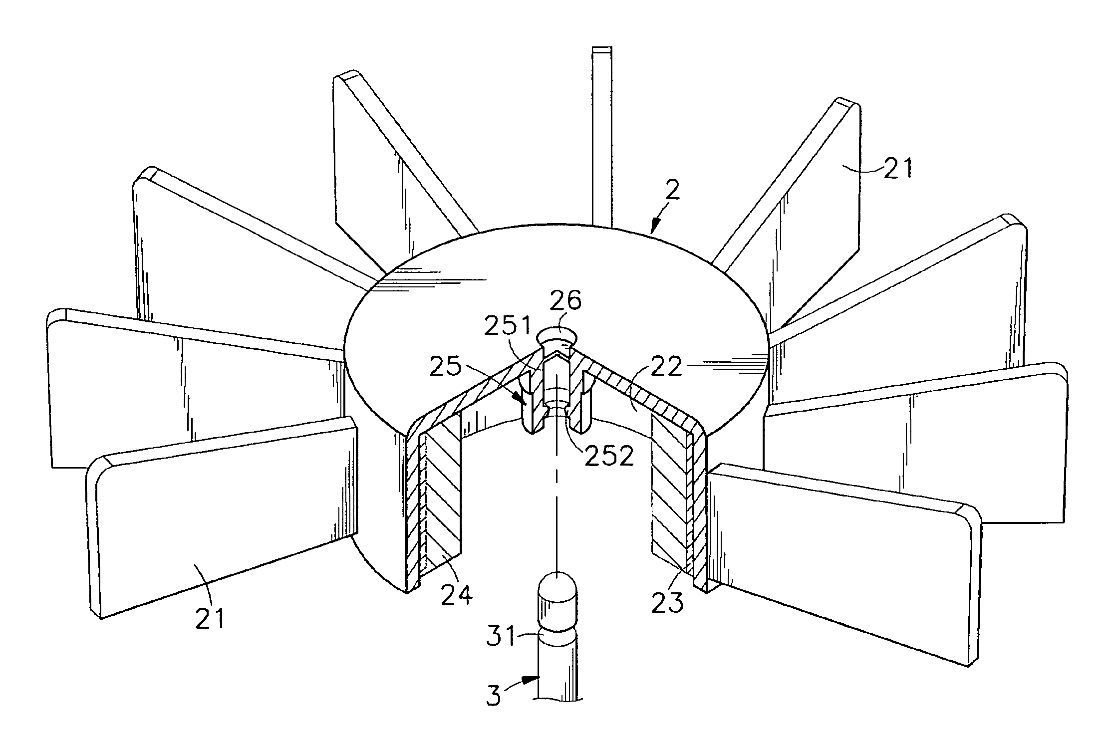
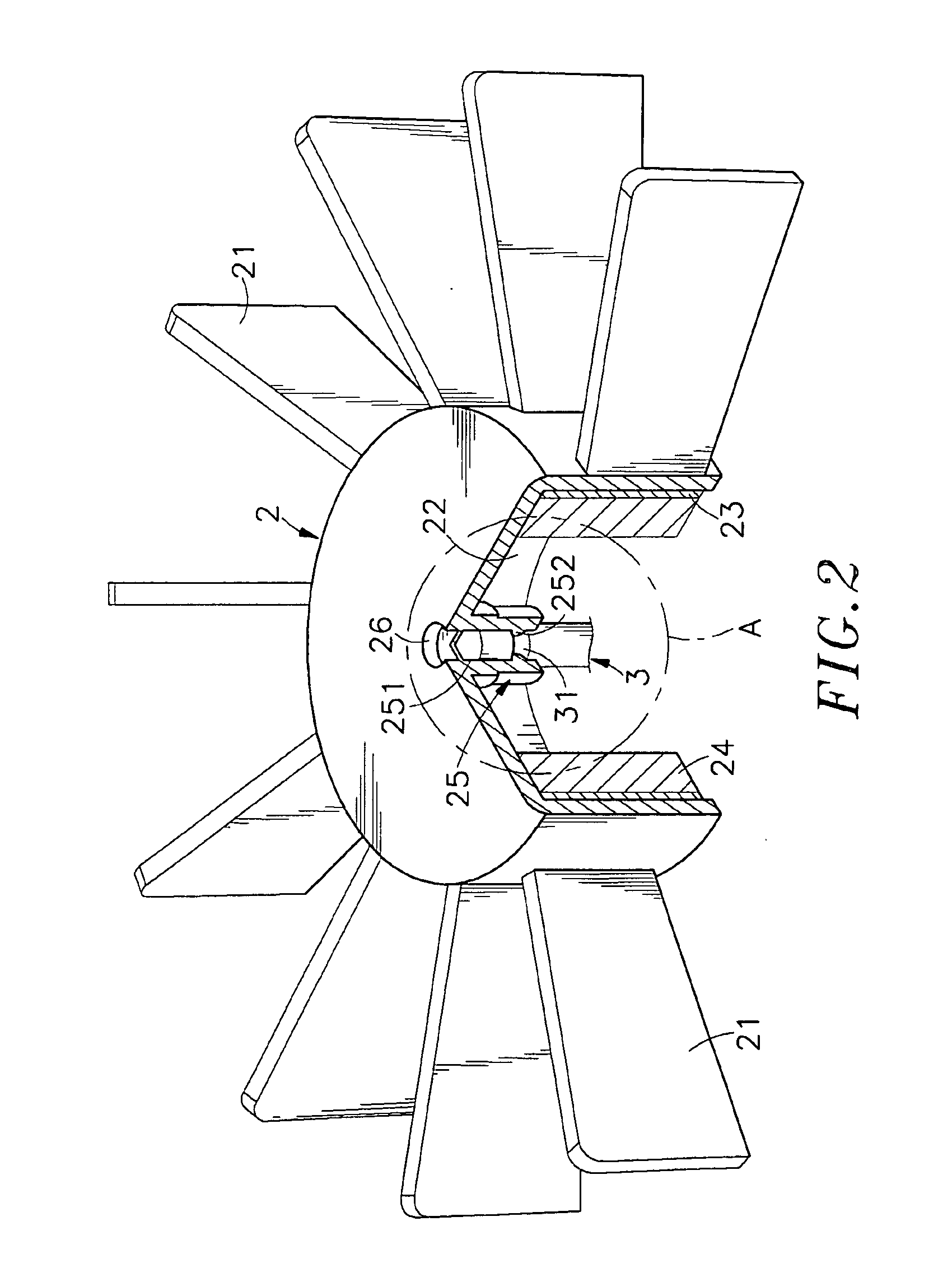
[0019]Referring to FIGS. 2˜4, a fan blade assembly in accordance with a first embodiment of the present invention is shown comprised of a fan blade body 2 and a core shaft 3.

[0020]The fan blade body 2 has an accommodation open chamber 22 disposed at the center and facing one side, namely, the bottom side, a plurality of radial blades 21 equiangularly spaced around the peripheral wall of the accommodation open chamber 22, a metal guide plate 23 mounted on the inner surface of the peripheral wall of the accommodation open chamber 22, a plurality of permanent magnets 24 affixed to the metal guide plate 23, a locating hole 26 located at the center of the top wall of the accommodation open chamber 22 and disposed outside the accommodation open chamber 22 for accommodating a magnetic member 27 (see FIG. 6), and an axle housing 25 downwardly extending from the center of the top wall of the accommodation chamber 22 opposite to the locating hole 26 and suspending inside the accommodation ope...


PUM


Abstract

A fan blade assembly includes a fan blade body, which has an axle housing downwardly suspending in a center accommodation open chamber thereof at the center and defining therein an axle hole and an inside annular flange in the axle hole, and a core shaft, which is inserted into the axle hole of the axle housing to support magnetic levitation rotation of the fan blade body and has a coupling groove extending around the periphery thereof and coupled to the inside annular flange of the axle housing with a gap left therebetween.

Description

[0001]This application claims the priority benefit of Taiwan patent application number 096217239 filed on Oct. 15, 2007.BACKGROUND OF THE INVENTION[0002]1. Field of the Invention[0003]The present invention relates to an electric fan and more specifically, to fan blade assembly, which facilitates accurate installation of the core shaft in the fan blade body for enabling the core shaft to support magnetic levitation rotation of the fan blade body stably.[0004]2. Description of the Related Art[0005]Cooling fans are intensively used in different electronic apparatus for quick dissipation of heat energy. When the mechanical operation speed of a cooling fan is increased, the noise level resulted from friction between the core shaft and the axle bearing is relatively increased. Excessive high temperature during operation of a cooling fan may cause burnout of the component parts.[0006]FIG. 1 illustrates a conventional magnetic levitation motor fan. According to this design, a fan blade asse...

Claims


Application Information

Patent Timeline
Patent Type & Authority Applications(United States)
IPC IPC(8): F01D5/34F01D25/28
CPCF04D29/057F04D25/062F04D29/058
Inventor KAO, MING-SHING
Owner HSU TING WEI MR
Learn More