
Method and apparatus for applying optical film to glass

a technology of optical film and glass, applied in the direction of paper hanging, mechanical control devices, instruments, etc., can solve the problems of difficult to create bevels on the edge of glass, difficult to cut beveled glass, and high cost of cutting beveled glass

Inactive Publication Date: 2005-03-22
GED INTEGRATED SOLUTIONS
View PDF24 Cites 36 Cited by
  • Summary
  • Abstract
  • Description
  • Claims
  • Application Information

AI Technical Summary

Benefits of technology

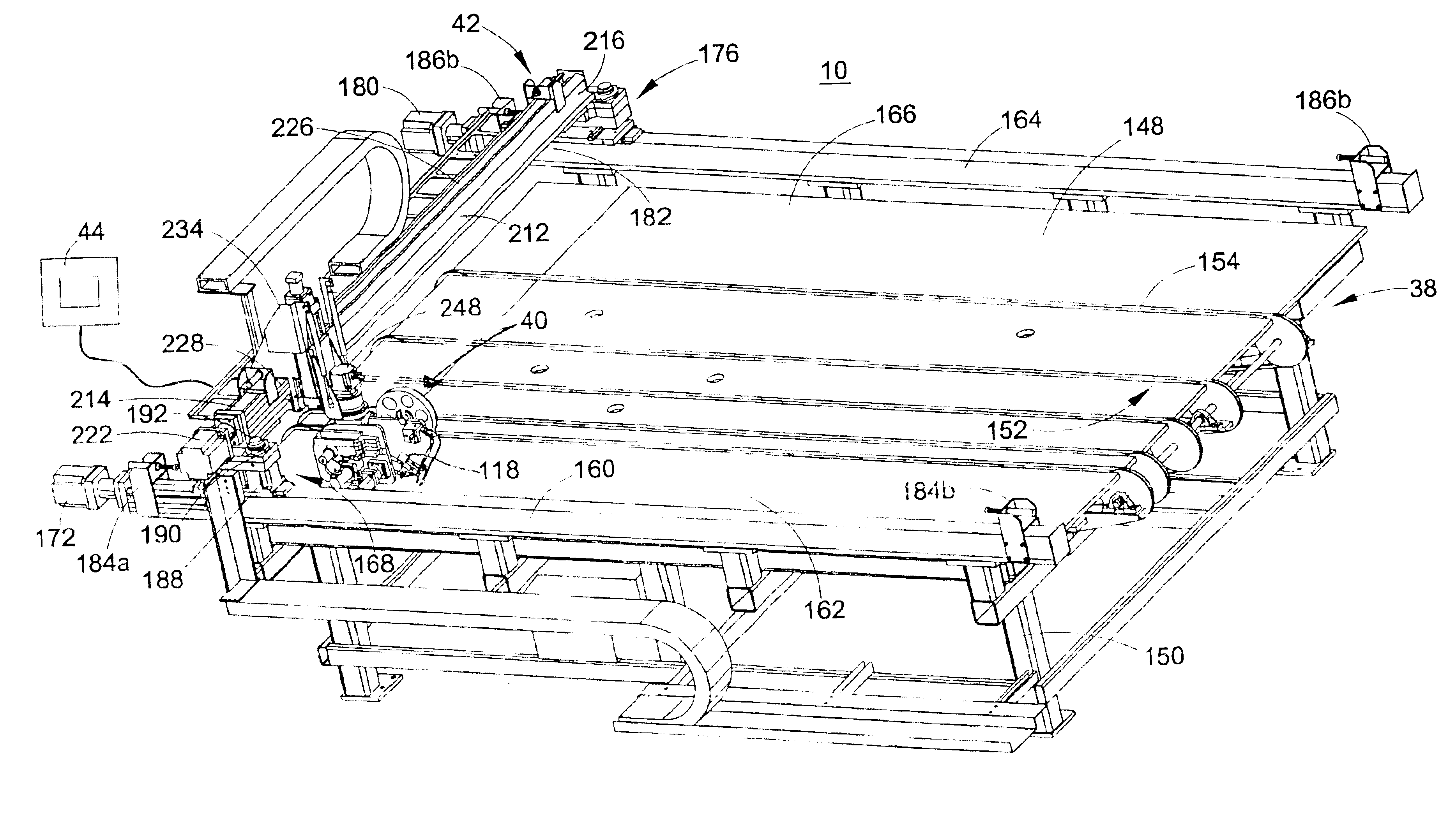
Embodiments of the tape dispenser include features that enhance the tape dispenser's ability to accurately apply tape to a glass surface. For example, the tape dispenser includes a slip clutch tensioner between the tape spool and the frame. A sensor is coupled to the drive roller that measures the length of the tape that travels past the drive roller. A pressure roller is rotatably mounted to the dispenser frame by a pneumatic actuator. The pressure roller is configured to apply pressure to the tape as the tape is applied to the glass. A position sensor is coupled to the pressure roller for determining a distance between the dispenser and the glass. An optical sensor is coupled to the dispenser frame for detecting edges of the glass to determine the size, location and orientation of the glass. A motor is coupled to the rewind spool by a slip clutch tensioner.
Embodiments of the tape application system enhance the ability of the system to accurately dispense tape onto glass plates. For example, a distance between the platen and the glass is sensed and the platen is moved to a predetermined distance from the glass in response to the sensed distance. A pressure application wheel is mounted to the dispenser and is movable into engagement with the glass plate. Variations in thickness of the glass caused the pressure application wheel to move with respect to the tape dispenser. A position sensor is coupled to the pressure application wheel and the dispenser actuator. Movement of the pressure application wheel is sensed by the position sensor and communicated to the dispenser actuator to move the dispenser to a predetermined distance above the glass plate.
The cassette used with the dispenser allows the tape to be changed very quickly. In addition, the cassette allows several widths of tape to be dispensed by the dispenser. The cassette can be used to change tape styles and sizes or additional cassette assemblies can be ready for reloading another roll of the same tape style.
The non contact glass light registration feature of the disclosed tape application system provides a precise indication of the location and orientation of the glass. This allows the tape to be precisely applied to the glass plate.

Problems solved by technology

Cut beveled glass is expensive due to the substantial labor involved in creating the bevel.
In addition, the process used to produce cut beveled glass tends to weaken the glass.
Consumers and glass manufacturers tend to avoid cutting bevels in a pane of glass because of the high degree of difficulty associated with cutting the bevel into the glass.
Tempered glass is hard and brittle, which makes it difficult to create a bevel on an edge of the glass.

Method used


Image

  • Method and apparatus for applying optical film to glass
  • Method and apparatus for applying optical film to glass
  • Method and apparatus for applying optical film to glass

Examples


Embodiment Construction

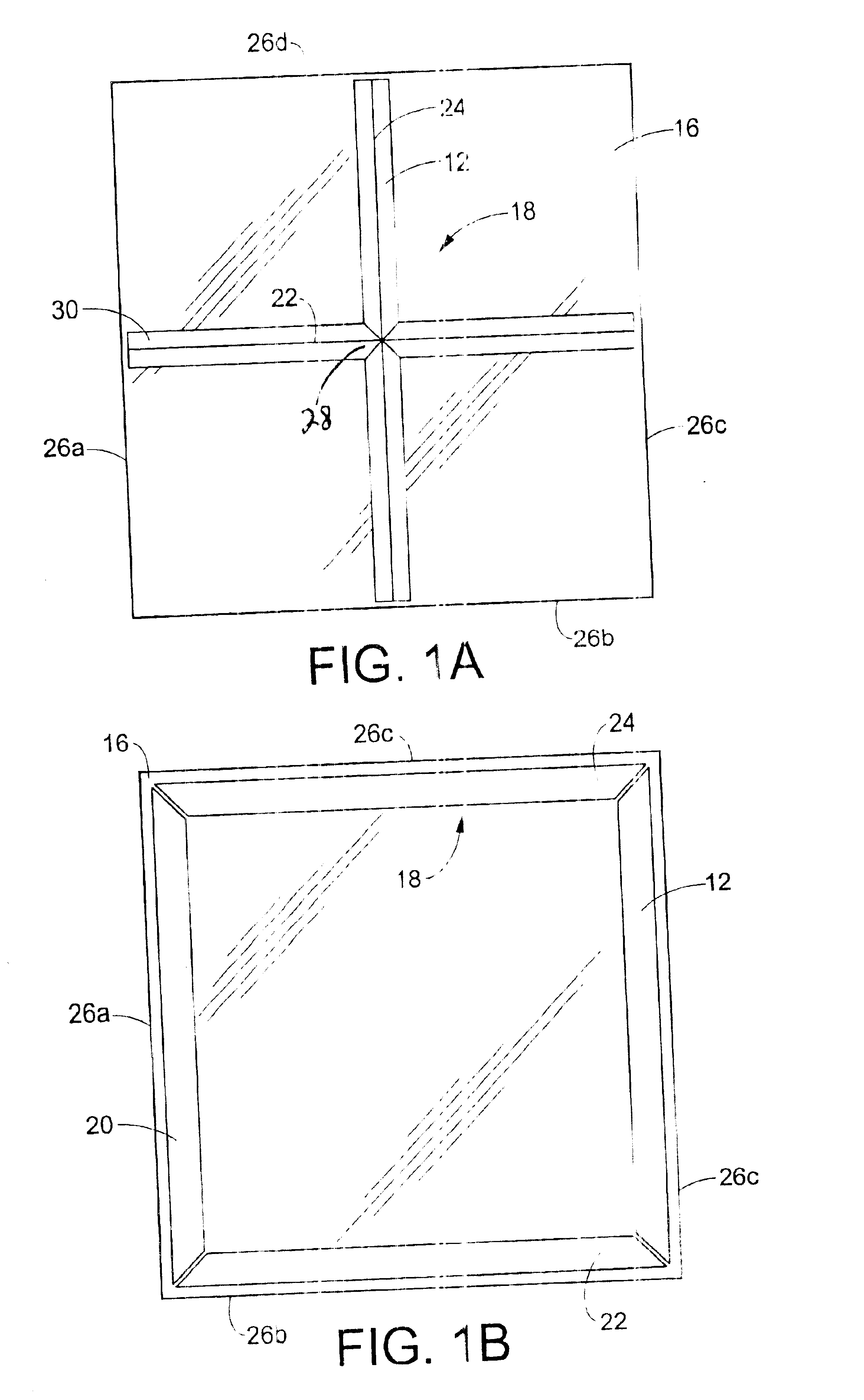
The present disclosure concerns a system 10 for applying tape 12 having a liner 14 or backing to a glass pane 16 in a decorative pattern 18. Examples of decorative tape patterns 18 applied to glass panes 16 by the disclosed system 10 are illustrated in FIGS. 1A and 1B. The decorative pattern 18 depicted in FIG. 1A creates the appearance of mitered glass. The decorative pattern depicted in FIG. 1B is referred to as a frame pattern 20. The frame pattern 20 creates the appearance of a beveled edge on the sides of the glass pane.

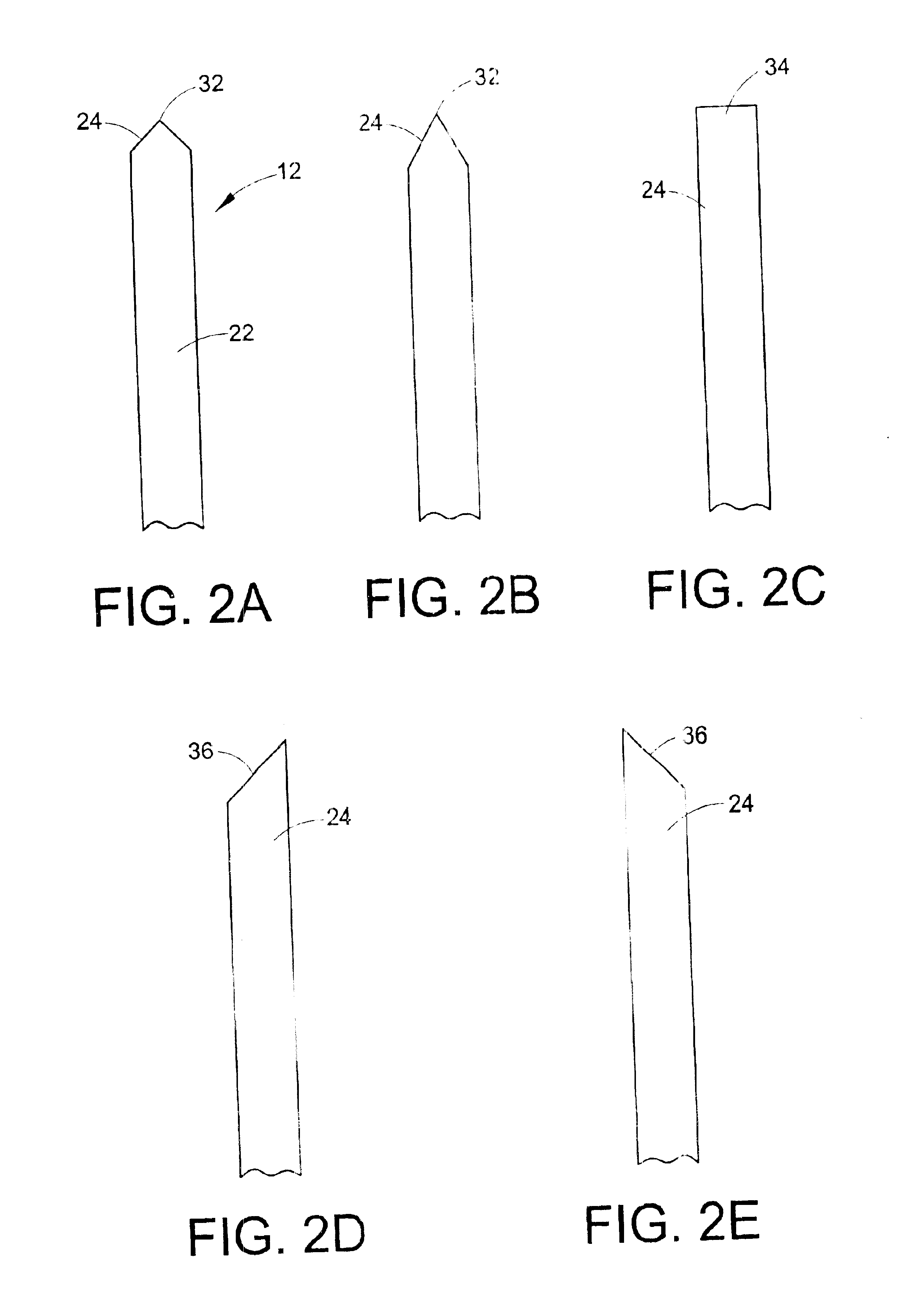
The decorative patterns 18 are created by applying strips 22 of tape 12 to the glass pane 16. In the illustrated embodiment, ends 24 of the tape 12 are cut to mate with ends of other pieces of tape or with edges 26a-d of the glass pane 16. The ends 24 of the strips 22 of tape are applied to the glass in close proximity with one another to give the appearance of a continuous bevel. For example, the central ends 28 of the strips that form the decorative pattern 18...


PUM

PropertyMeasurementUnit
lengthaaaaaaaaaa
pressureaaaaaaaaaa
distanceaaaaaaaaaa

Abstract

A tape dispenser for precisely applying decorative tape for creating the appearance of a bevel onto a glass surface. The tape dispenser includes a frame, a tape spool rotatably mounted to the frame, a drive roller rotatably mounted to said frame for controlling a length of such tape unwound from said tape spool, a platen having an angular front end portion that causes a liner to separate from the tape, and a rewind spool rotatably mounted to the frame. The tape spool, drive roller, platen and rewind spool define a path of travel from the tape spool, around the drive roller, around the front end portion of said platen, to said rewind spool.

Description

FIELD OF THE INVENTIONThe present invention relates a method and apparatus for applying decorative tape to glass and, more particularly, the present invention relates to an automated method and apparatus for precisely applying a tape that gives the appearance of cut beveled glass to a glass plate.BACKGROUND OF THE INVENTIONCut beveled glass is used for decorative purposes in a variety of applications, such as, in windows, doors, tables and mirrors. Cut beveled glass is expensive due to the substantial labor involved in creating the bevel. In addition, the process used to produce cut beveled glass tends to weaken the glass. It is necessary for glass manufacturers to use thicker, more expensive, glass when manufacturing beveled glass to ensure the outside edge of the bevel meets minimum thickness standards. Consumers and glass manufacturers tend to avoid cutting bevels in a pane of glass because of the high degree of difficulty associated with cutting the bevel into the glass.Tempered...

Claims


Application Information

Patent Timeline
Patent Type & Authority Patents(United States)
IPC IPC(8): B65H37/00B65H35/00
CPCB65H35/0013B65H37/002Y10T156/1795Y10T156/12Y10T156/1348B26D2007/0068
Inventor BRIESE, WILLIAM A.
Owner GED INTEGRATED SOLUTIONS
Learn More