
Method and device for utilizing the waste heat that has accumulated during the supply of forced draught/compressed air to a printing press

a printing press and waste heat technology, applied in the field of waste heat accumulating during the supply of forced draught/compressed air to the printing press, can solve the problems of high cost, disadvantageous air value fluctuation, and air taken in not always meeting the criteria provided for the printing process, so as to increase the temperature and save costs

Inactive Publication Date: 2005-03-22
GEBRR BECKER +1
View PDF16 Cites 5 Cited by
  • Summary
  • Abstract
  • Description
  • Claims
  • Application Information

AI Technical Summary

Benefits of technology

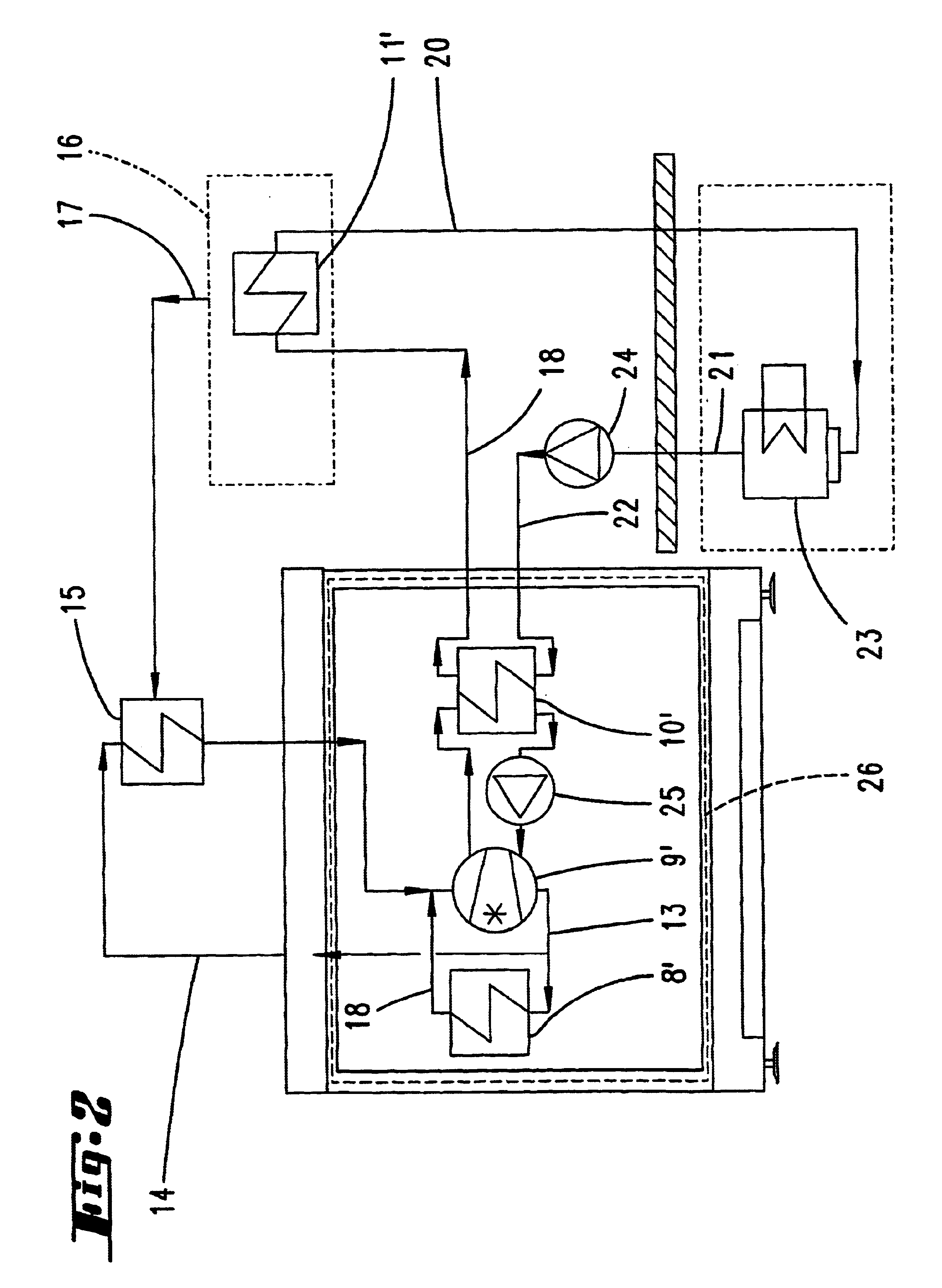
This object is achieved in that the heated waste air discharged after passing through the subassemblies and the cooling air is cooled by means of a heat exchanger / refrigerant, the refrigerant is then brought to a considerably higher temperature level, in order to increase the temperature, and, furthermore, air which is required for the drier is heated up in a second heat exchanger. This method, on the one hand, makes it possible, by virtue of the air which serves for supplying the compressors being cooled, to carry out a certain conditioning, if required, that is to say to cool, if necessary, to below the dew point of this air. On the other hand, however, the heat obtained in this way continues to be used, that is to say costs may be saved elsewhere, this being the case in respect of the drying air which is also necessary in a printing machine.
It is also particularly important that the cooling and transformation is carried out by means of a circulating refrigerant. Thus, on the one hand, the complete separation of the two circuits is ensured but, on the other hand, reliable transformation, precisely in the heat-pump process, is made possible.

Problems solved by technology

The disadvantage in all cases, however, is that the air taken in does not always fulfill the criteria provided for the printing process, in view in particular of the paper used there.
It is predominantly also the fluctuation in the air values (temperature, humidity) which is disadvantageous.
However, this involves very high outlay.

Method used


Image

  • Method and device for utilizing the waste heat that has accumulated during the supply of forced draught/compressed air to a printing press
  • Method and device for utilizing the waste heat that has accumulated during the supply of forced draught/compressed air to a printing press
  • Method and device for utilizing the waste heat that has accumulated during the supply of forced draught/compressed air to a printing press

Examples


Embodiment Construction

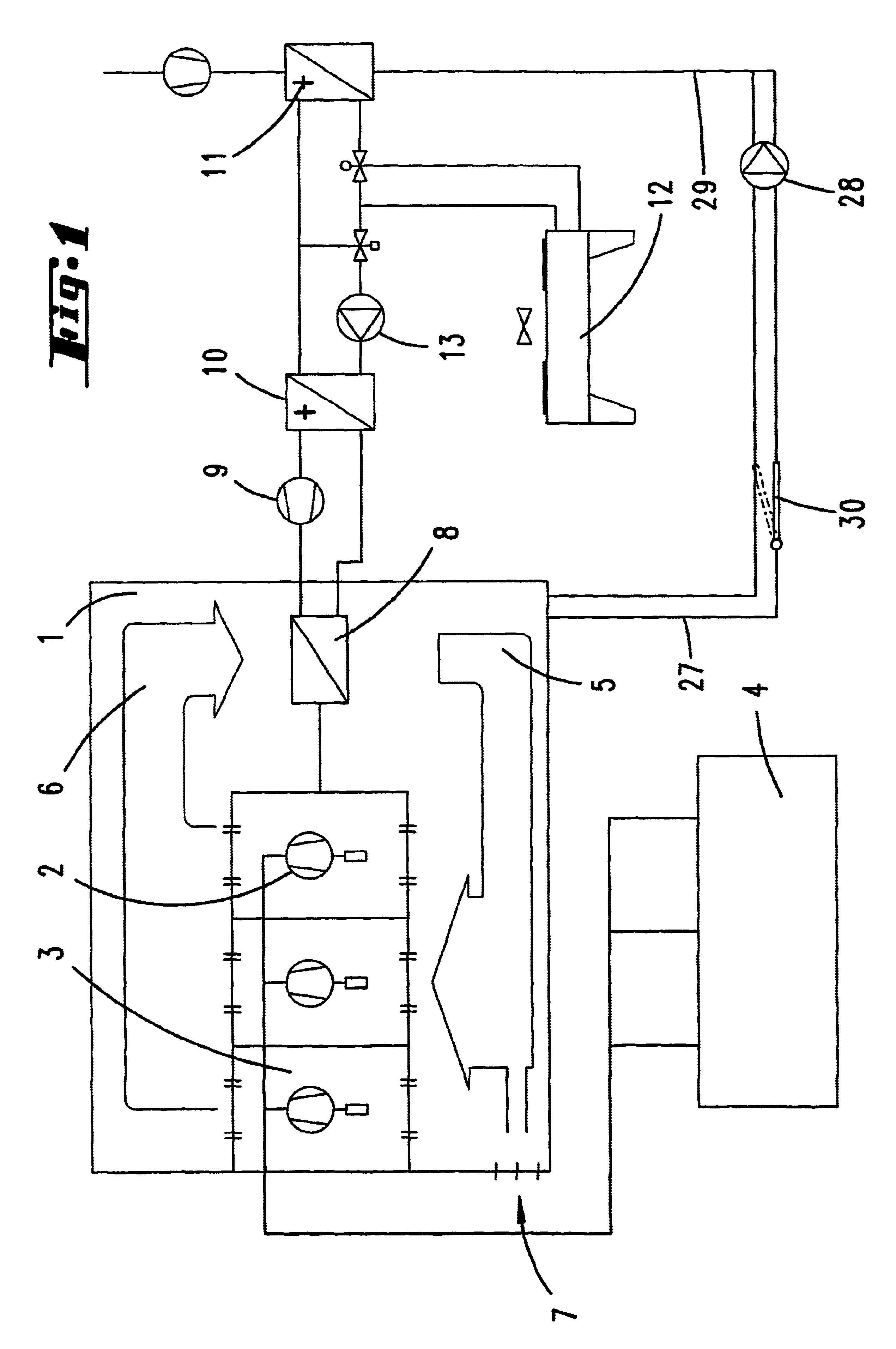
Illustrated and described, in the first instance with reference to FIG. 1, is a separate room 1 in which a plurality of compressors 2 and, if appropriate, vacuum pumps 3 are located for supplying a printing machine 4 with compressed air and a vacuum. The blower 2 is supplied with the necessary air predominantly by circulating-air operation, which is indicated by the arrows 5, 6. The separate housing, rather than being hermetically sealed, also has ambient openings 7, in order to balance the air supply.

The heated circulating air, which flows in accordance with the arrow 6, is routed through a heat exchanger 8, in which it is cooled by means of a refrigerant.

In the case of a practical application example, the cooling air leaves the vacuum pumps and compressors, by means of fans, at a temperature of approximately 30° C. and is cooled again to approximately 15° C. in the heat exchanger 8, this being the case for a quantity of air per fan / blower of approximately 2500 m3 per hour, that is...


PUM


Abstract

A method of and installation for supplying suction / compressed air and drying air to a printing machine, whereby the vacuum pumps and compressors which are necessary for supplying the suction air / compressed air are disposed together in a room with a separate air supply, wherein to homogenize if required condition air without extra costs the cooling air for the vacuum pumps or compressors is conducted substantially in a circuit, and the heated exhaust air of the vacuum pumps and the heated cooling air of the vacuum pumps and compressors are cooled in a heat exchanger and used for heating separate drying air.

Description

FIELD AND BACKGROUND OF THE INVENTIONThe invention relates in the first instance to a method of using the waste heat which accumulates when suction air / compressed air is supplied to a printing machine, the subassemblies which produce the suction air and / or compressed air being disposed together in a room with a separate air supply.Such air-supply arrangements for printing machines are known. It is also known for these to be disposed in a room with a separate air supply, although a large part of the necessary air is taken in from the surroundings, in particular also from the hall in which the printing machine is set up. It has also already been proposed for the subassemblies to be set up in a separate room outside the hall and to take in the corresponding quality of air from these surroundings.The disadvantage in all cases, however, is that the air taken in does not always fulfill the criteria provided for the printing process, in view in particular of the paper used there. It is pre...

Claims


Application Information

Patent Timeline
Patent Type & Authority Patents(United States)
IPC IPC(8): B01D53/26B41F13/00B41F23/04F24F3/14
CPCB01D53/26B41F13/00Y02B30/52
Inventor HENNING, HANS-HEINRICHRADERMACHER, BERNHARDWINKELSTROTER, WALTERSCHAFER, DIRKWERTH, MICHAELMOHR, WOLFGANG
Owner GEBRR BECKER
Learn More