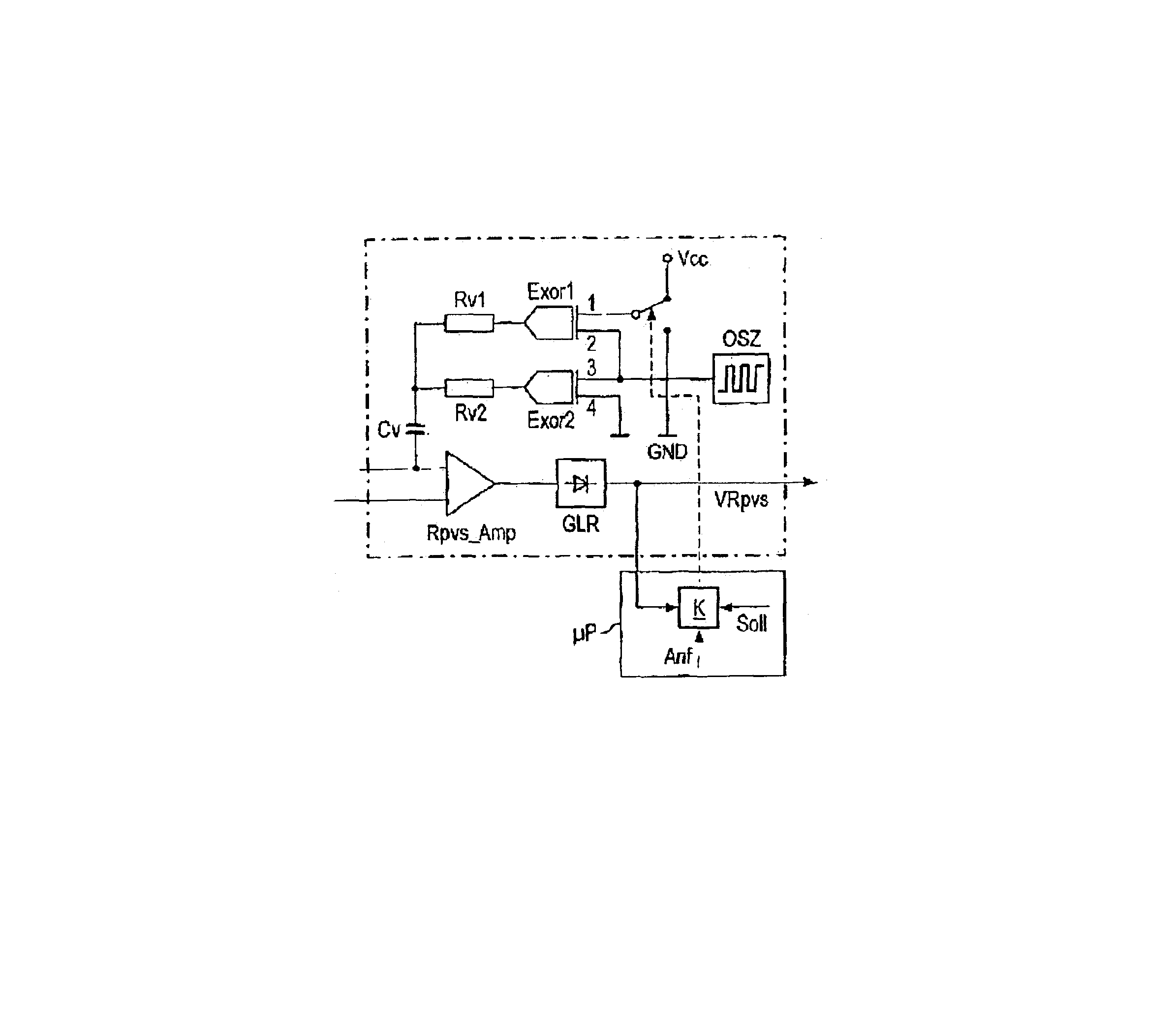
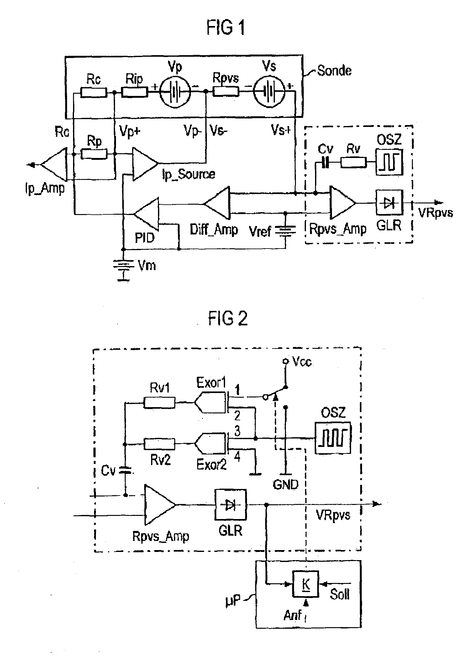
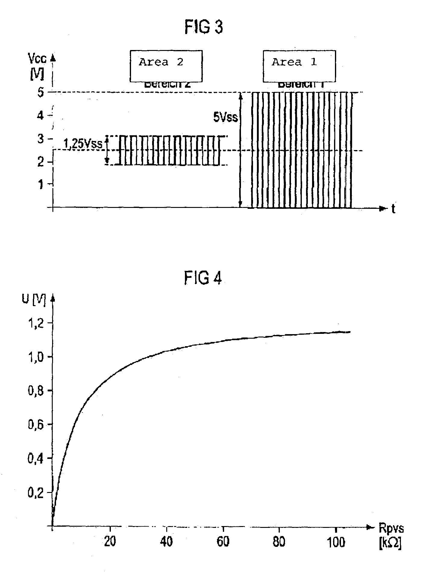
This object can be achieved by a device for determining the internal resistance of a linear oxygen probe of an internal combustion engine, comprising an oscillator for producing an alternating current which is superimposed on the probe internal resistance through a decoupling capacitor via a probe terminal and which, after being amplified in an amplifier then rectified, generates a voltage proportional to the probe internal resistance as a regulating signal for a probe heater, and a voltage divider to whose two terminals the oscillator output signal is supplied which produces a voltage at its tap which generates the alternating current flowing through the probe internal resistor, wherein the output signal of the oscillator with a phase position that is mutually opposed is supplied to the two terminals of the voltage divider from the time the operating voltage is switched on, through which the oxygen probe is heated, until the voltage at the output of the amplifier that is proportional to the probe internal resistance falls below a pre-determined set value, and at this point in time the output signal of the oscillator is supplied to both terminals of the voltage divider with the same phase position.
The device may further comprise a first Exclusive-OR element whose input can be connected via a change-over switch to the high potential or low potential of an operating voltage, and whose other input is connected to the output of the oscillators, and a second Exclusive-OR element whose input is connected to the output of the oscillator and whose other input is connected to low potential, the output of the first Exclusive-OR element is connected to the output of the second Exclusive-OR element via the voltage divider formed by connecting a first resistor and second resistor in series, wherein the tap of the voltage divider, the junction of the two resistors, is connected to the probe terminal and the input of the amplifier via the decoupling capacitor. The device may further comprise a comparator to which the output voltage, a pre-determined set value, and an instruction are supplied, which connects input of the first Exclusive-OR element via the change-over switch to the high potential of the operating voltage, when the operating voltage is switched on at the start of operation and for as long as the output voltage exceeds the set value, and which applies input of the first Exclusive-OR element via the change-over switch to low potential of the operating voltage, as soon as the output voltage falls below the set value. The set value may be selected such that the output voltage is less than the high potential after the change-over switch has changed over from high potential to low potential.
The object can also be achieved by a device for determining the internal resistance of a linear oxygen probe of an internal combustion engine, comprising an oscillator generating an alternating current output signal, a controllable phase shifter for generating an in-phase oscillator output signal or an opposite phase oscillator output signal, a voltage divider receiving the oscillator output signal and the phase shifter output signal, a decoupling capacitor superimposing the divided output signal on a probe internal resistance, an amplifier coupled with the probe for amplifying the probe signal, a rectifier coupled with the amplifier for rectifying the amplified signal, and a comparator for comparing a voltage proportional to the probe internal resistance with a predetermined value to generate a control signal for the phase shifter.
The device may further comprise a first Exclusive-OR element whose input can be connected via a change-over switch to the high potential or low potential of an operating voltage, and whose other input is connected to the output of the oscillators, and a second Exclusive-OR element whose input is connected to the output of the oscillator and whose other input is connected to low potential, the output of the first Exclusive-OR element is connected to the output of the second Exclusive-OR element via the voltage divider formed by connecting a first resistor and second resistor in series, wherein the tap of the voltage divider, the junction of the two resistors, is connected to the probe terminal and the input of the amplifier via the decoupling capacitor. The device may further comprise a comparator to which the output voltage, a pre-determined set value, and an instruction are supplied, which connects input of the first Exclusive-OR element via the change-over switch to the high potential of the operating voltage, when the operating voltage is switched on at the start of operation and for as long as the output voltage exceeds the set value, and which applies input of the first Exclusive-OR element via the change-over switch to low potential of the operating voltage, as soon as the output voltage falls below the set value. The set value may be selected such that the output voltage is less than the high potential after the change-over switch has changed over from high potential to low potential. The controllable phase shifter may comprise an EXOR gate receiving the oscillator output signal and a logical signal as a control signal.
The object may also be achieved by a method for operating a linear oxygen probe of an internal combustion engine, comprising the steps of:generating a first and second alternating current wherein the second alternating current is either in-phase or opposite phase to the first alternating current,combining the first and second alternating currents by means of a voltage divider,superimposing the combined signal on the probe internal resistance,amplifying and rectifying a probe signal;comparing the probe amplified and rectified signal with a threshold value;depending on the comparison switching the second alternating current to be in-phase or opposite phase.
The step of superimposing can be performed by means of a capacitor. The switching may be performed by means of a logic signal. The threshold value can be selected such that the output voltage is less than the high potential of the logic signal after the change-over switch has changed over from high potential to low potential.


