
Air-conditioning control apparatus using heater

Active Publication Date: 2005-03-22
HITACHI PLANT SERVICES
View PDF9 Cites 5 Cited by
  • Summary
  • Abstract
  • Description
  • Claims
  • Application Information

AI Technical Summary

Benefits of technology

The present invention has been devised in view of such circumstances, and it is an object of the present invention to provide a heater with increased quick responsiveness to temperature control of air, and to provide an air conditioner which can realize highly accurate temperature control using this heater.
According to the present invention, since heat generated by lighting the electric lamp is used as the heat source for the heater, quick responsiveness to temperature control is improved.
According to the present invention, at least two heaters, that is, the additional heater (first heater) and the heater with the electric lamp (second heater) are provided in the supply path and the temperature sensors for controlling the first and second heaters are attached to the predetermined positions of the supply path and the air-conditioned room, respectively, whereby temperature control in two stages with different temperature resolutions is realized. Thus, an air conditioner which can control temperature of the air-conditioned room with high accuracy can be provided. That is, air taken into the supply path is first heated to a temperature close to a temperature required for the air-conditioned room by the first heater and, then, temperature of the air is controlled, for example, by a unit in the order of {fraction (1 / 1000)}° C. by the second heater with the higher resolution to supply this air to a predetermined position of the air-conditioned room. Consequently, air-conditioning air, which is subjected to highly accurate temperature control to have fluctuation of temperature eliminated, can be supplied to the air-conditioned room.
According to the present invention, since the heater is provided in the duct unit, the duct unit only has to be removed from the supply path when the entire heater is repaired or replaced. Thus, replacement work is facilitated. If the cover is opened to remove the heater from the duct unit, maintenance of each member of the heater can be performed.

Problems solved by technology

However, the conventional heater has a disadvantage in that it is poor in quick responsiveness to temperature control because it uses the heat transfer wire and is not suitable for an environment in which highly accurate temperature control is desired.
Moreover, since the conventional cooler controls temperature of air by controlling a flow rate of supply of chilled fluid to be supplied to the cooling coil, it is difficult to control a flow rate of chilled fluid with respect to controlled temperature of the air.
For example, the cooler is poor in quick responsiveness to a change in temperature due to external factors such as an outflow of air caused by opening and closing of a door of a precision environment chamber and is further unsuitable for controlling temperature with high accuracy.
Further, there is a disadvantage in that quick responsiveness cannot be expected with respect to a change in temperature due to external factors as described above simply by providing a heater or a cooler having a single temperature resolution.
Furthermore, there is a disadvantage in that, if a plurality of heaters and coolers are provided excessively, control becomes complicated and costs of equipment increase.

Method used


Image

  • Air-conditioning control apparatus using heater
  • Air-conditioning control apparatus using heater
  • Air-conditioning control apparatus using heater

Examples


Embodiment Construction

A preferred embodiment of a heater in accordance with the present invention and an air conditioner using this heater will be hereinafter described with reference to the accompanying drawings.

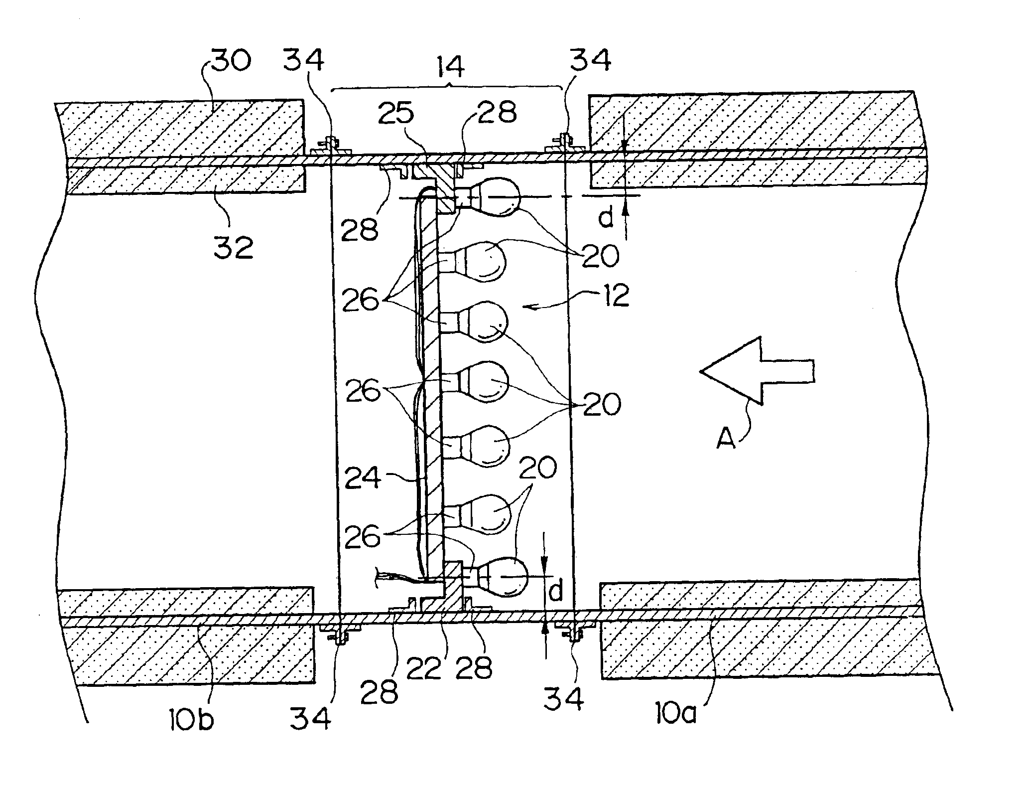
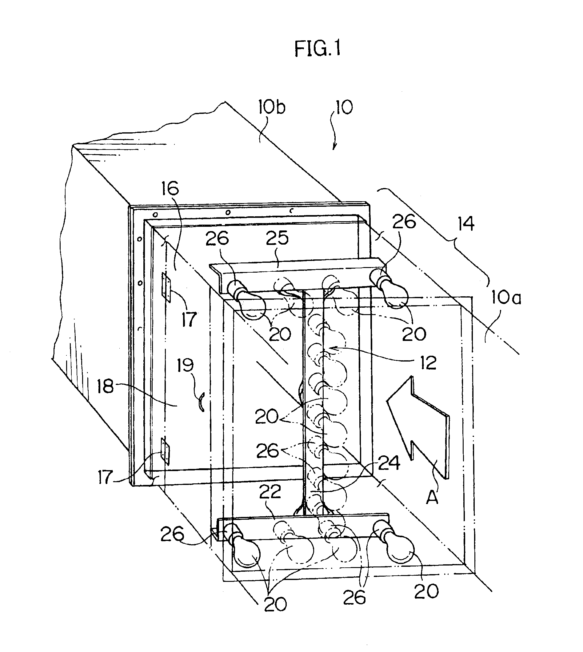
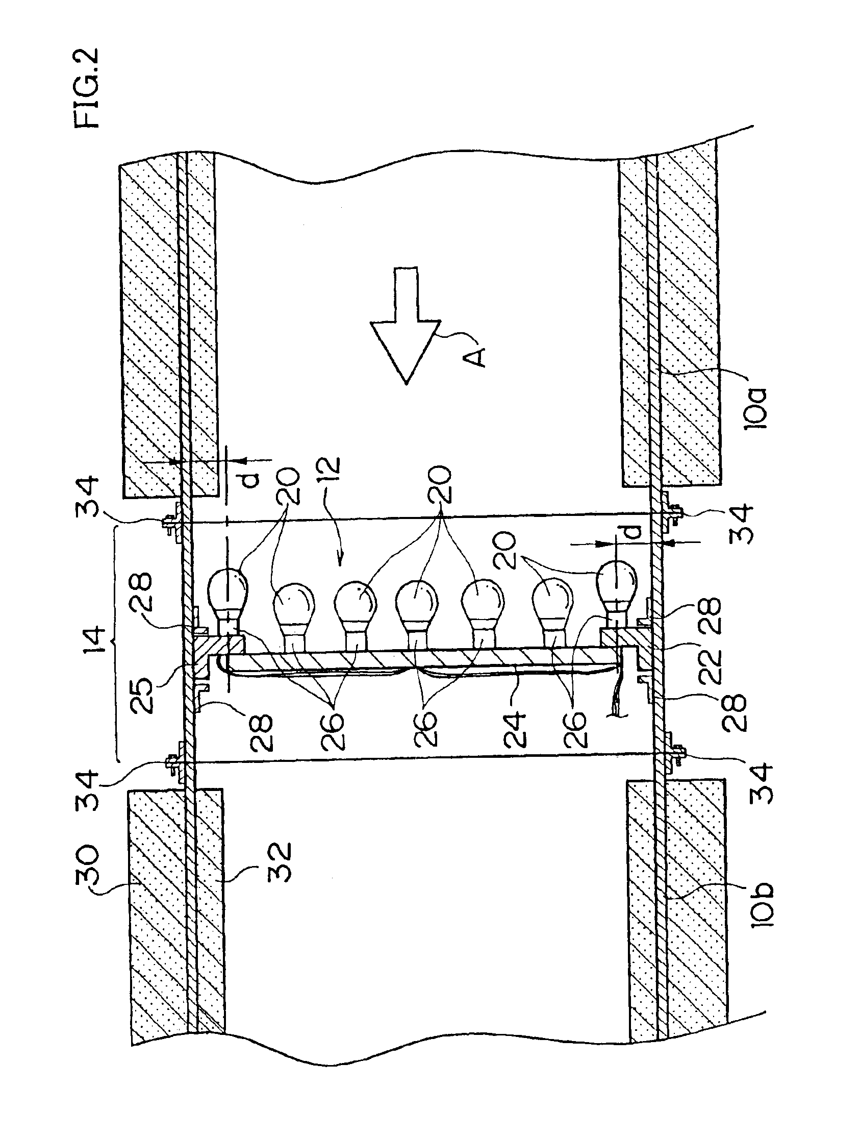
FIG. 1 is a perspective view showing an example in which a heater according to an embodiment of the present invention is provided in an air duct 10 (supply path). As shown in FIG. 1, the air duct 10 includes a duct unit 14 provided with a heater 12, and an upstream side air duct 10a and a downstream side air duct 10b detachably coupled to the duct unit 14. Air supplied from the upstream side air duct 10a is heated by the heater 12 and then flows to the downstream side air duct 10b.

A rectangular opening 16 for removing the heater 12 is formed on a side of the duct unit 14, and a cover 18 for opening and closing the opening 16 is attached to the side of the duct unit 14 via hinges 17. A handle 19 is attached to the cover 18, and the cover 18 can be locked and unlocked by a lock mechanism (not sho...


PUM


Abstract

The heater has increased quick responsiveness to temperature control of air, and the air conditioner can realize highly accurate temperature control using the heater. A duct unit having heat sources comprising electric lamps in the inside thereof is attached to an air duct. Air coming into contact with glass bulbs of the electric lamps is heated by radiant heat and transferred heat generated by lighting the electric lamps, whereby the heater with increased quick responsiveness to temperature control is obtained. A first heater and a second heater are provided in the air duct, respectively, and temperature sensors for controlling these heaters are attached to the air duct and a precision environment chamber, respectively, whereby temperature control in two stages with different temperature resolutions is made possible, and an air conditioner with high accuracy excellent in controllability can be provided.

Description

BACKGROUND OF THE INVENTION1. Field of the InventionThe present invention relates to an air conditioner using a heater, and in particular to an air conditioner which uses a heater provided with heat sources in the inside thereof for heating air to be supplied, and controls air-conditioning so as to keep a room temperature of an air-conditioned room constant.2. Description of the Related ArtIn a clean room (air-conditioned room) used in a semiconductor manufacturing factory or the like, conditions required for working environment tend to be strict. For example, in a precision environment chamber or the like, temperature control in the chamber is required strictly. In particular, in a space where inspection work or the like is actually carried out in the room, highly accurate temperature control is required for an air conditioner, for example, fluctuation of temperature in the space is required to be controlled to ±{fraction (1 / 1000)}° C. or less.Japanese Patent Application Publicatio...

Claims


Application Information

Patent Timeline
IPC IPC(8): F24H3/04F24F3/044F24F3/056H05B3/00F24F11/02
CPCF24F3/056H05B3/008F24H3/0405F24F2221/54F24H3/04
Inventor SAKUMA, MASAYOSHIGOTOUDA, RYUUSUKEWATANABE, KOUJITAKAHASHI, MINORUKAWAI, HIDENAOONODERA, TOSHIOJOUKOU, KATSUHIROKIMOTO, YOSHIHIROSHIMOKAWA, YUTAKATANAKA, MAKOTO
Owner HITACHI PLANT SERVICES
Learn More