Eureka AIR delivers breakthrough ideas for toughest innovation challenges, trusted by R&D personnel around the world.

System and method for median fusion of depth maps

a technology of depth map and system, applied in the field of system and method for creating graphical models from video sequences, can solve the problems of limiting the views or images that are available, inability to dynamically modify, and inaccuracy of the output graphics,

Inactive Publication Date: 2005-03-15
TELEFON AB LM ERICSSON (PUBL)
View PDF11 Cites 27 Cited by
  • Summary
  • Abstract
  • Description
  • Claims
  • Application Information

AI Technical Summary

Benefits of technology

The present invention is directed toward a system and method for computing a refined depth map for a spatial representation from a plurality of estimated depth maps. The system utilizes information in multiple depth maps of a represented image to refine an optimum depth map, selecting the median depth value for each pixel in each depth map rendered into a new view. The system determines the median depth map value for each pixel by selecting the rendered pixel depth value that is the median value among all the respective pixels from the rendered depth maps, which are fused one at a time with the new view of the object or scene. The resulting median fused depth map can be used to more accurately represent a graphical or video image as perceived from the new view.

Problems solved by technology

While recent advances in computer processing power and data-handling capability have improved computerized 3D modeling, these graphical 3D construction systems remain characterized by demands for heavy computer processing power, large data storage requirements, and long processing times. Furthermore, volumetric representations of space, such as a graphical 3D model, are not easily amenable to dynamic modification, such as combining the 3D model with a second 3D model or perceiving the space from a new view or center of projection.
However, calibration estimation inserts an additional variable in the 3D graphical model rendering process that can cause inaccuracies in the output graphics.
Furthermore, calibration of the camera views necessarily requires prior knowledge of the camera movement and / or orientation, which limits the views or images that are available to construct the 3D model by extrapolating the calibrated views to a new location.
However, shape information recovered from only two views of an object is neither complete nor very accurate, so it is often necessary to incorporate images from additional views to refine the shape of the 3D model.
However, such manipulation is a manual process, which not only limits the automated computation of composite graphical images but also risks introducing errors as the appropriate level of weighting, warping, and / or blending is estimated.
However, since the estimated depth maps invariably contain errors, there is no guarantee that the maps will be consistent with each other and will match where they should.
Furthermore, conventional practices of stereo mapping with depth maps stop the refinement process at the estimation of a single depth map.

Method used


Image

  • System and method for median fusion of depth maps
  • System and method for median fusion of depth maps
  • System and method for median fusion of depth maps

Examples


Embodiment Construction

In the following description, for purposes of explanation and not limitation, specific details are set forth in order to provide a thorough understanding of the present invention. However, it will be apparent to one skilled in the art that the present invention may be practiced in other embodiments that depart from these specific details. In other instances, detailed descriptions of well-known methods, devices, and circuits are omitted so as not to obscure the description of the present invention.

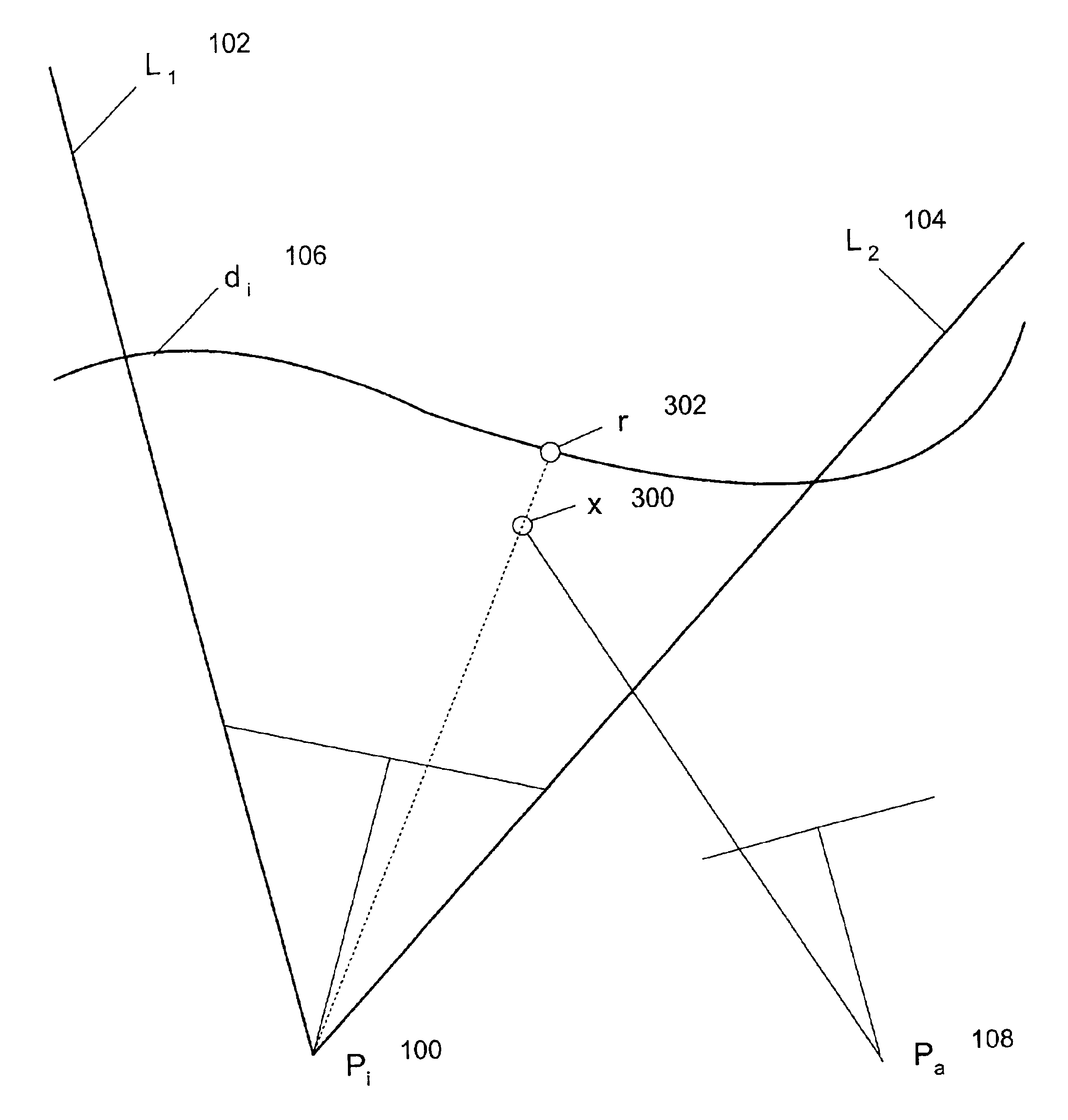
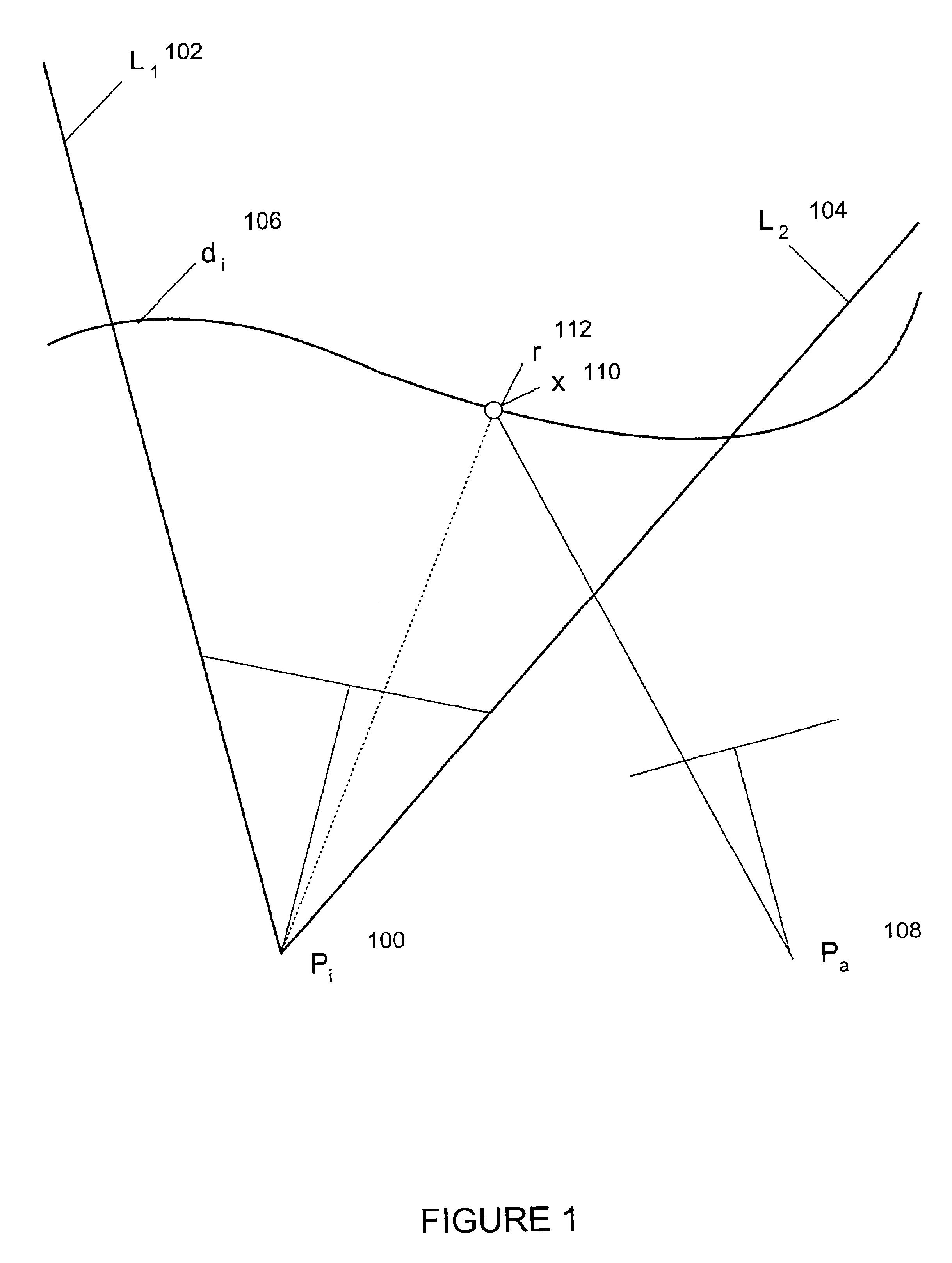
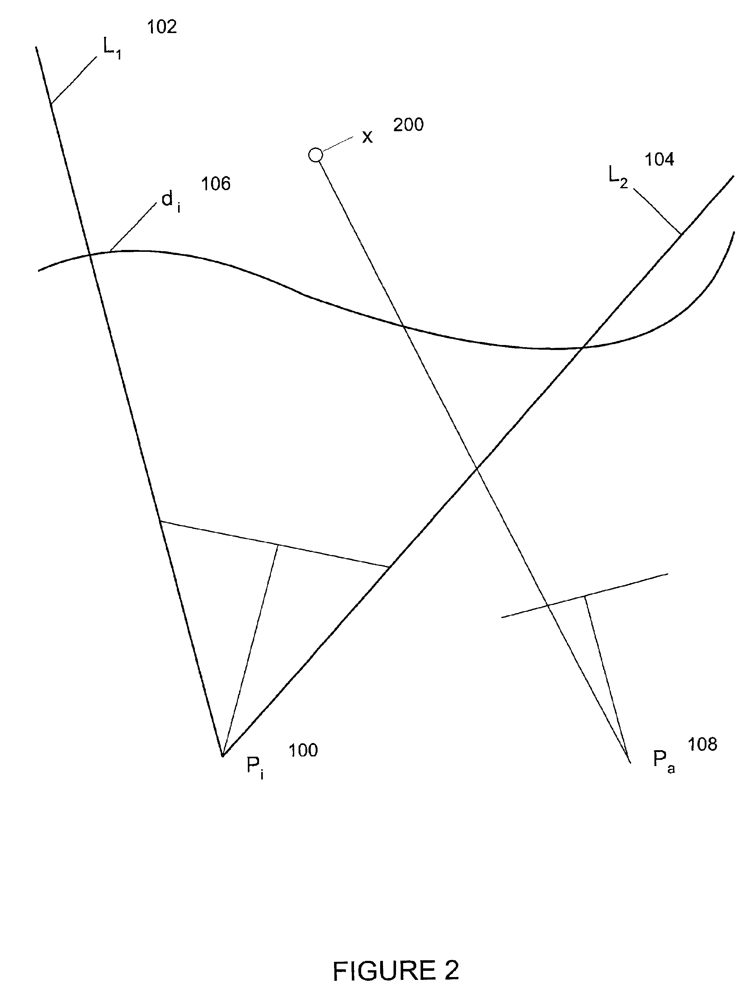
While the present invention can be utilized for determining fused depth maps of virtually any object or scene and for constructing 3D images of such objects and scenes, the discussion below will refer to all such 3D items as “objects” to simplify the explanation of the embodiments of the invention. Referring now initially to FIG. 1, there is shown a portion of an object as perceived from view i. The line segment, di 106 represents the view of the object as seen from view i, in the image pla...


PUM


Abstract

The present invention is directed toward providing a system for constructing a graphical representation of an image, as perceived from a desired view, from a plurality of calibrated views. An optimum, median fused depth map of a new, desired view of an object or a scene is constructed from a plurality of depth maps of the object or scene, utilizing median values for each of the image pixels within the image domain of the new view. Each of the known depth maps are rendered into the new view, and the pixels of the rendered image are processed one at a time until a median value for each pixel in the new view of the image of the object or scene is calculated. The calculated median values are then assembled into a median fused depth map of the new view of the object or scene, with the median fused depth map available to construct a new two or three dimension images and models of the object or scene as perceived from the new view.

Description

BACKGROUND OF THE INVENTION1. Field of the InventionThe present invention relates generally to systems for creating graphical models from video sequences, and more particularly, to a system for constructing a refined graphical representation of an image from a plurality of calibrated camera views.2. Background InformationComputer-aided imagery is the process of rendering new two-dimension and three-dimension images on a terminal screen or graphical user interface from two or more digitized two-dimension images with the assistance of the processing and data handling capabilities of a computer. Constructing a three-dimension (hereinafter “3D”) model from two-dimension (hereinafter “2D”) images is utilized, for example, in computer-aided design (hereinafter “CAD”), 3D teleshopping, and virtual reality systems, in which the goal of the processing is a graphical 3D model of an object or a scene that was originally represented only by a finite number of 2D images. Under this application o...

Claims


Application Information

Patent Timeline
IPC IPC(8): G06T15/20G06T15/10G06T1/00G06T7/00
CPCG06T15/20G06T7/0065G06T7/55
Inventor NISTER, DAVID
Owner TELEFON AB LM ERICSSON (PUBL)
Why Eureka
Eureka Blog
Learn More