Method and apparatus for testing flow and flushing a transmission cooling system

Inactive Publication Date: 2005-03-15
SPX CORP
View PDF9 Cites 0 Cited by
  • Summary
  • Abstract
  • Description
  • Claims
  • Application Information

AI Technical Summary

Benefits of technology

The foregoing need has been met by the present invention, whereby in one aspect of the invention, a method is provided to test flow and flush a cooling system. The method includes pressurizing transmission fluid to create fluid flow and regulating the fluid flow direction through a fluid control system. A fluid flow rate measurement is ascertained in order to determine whether the fluid is flowing at a proper rate. If the fluid flow rate is inadequate, turbulence is added to the fluid flow, and the cooling system is flushed by the fluid in a flow direction through the cooling system. The flushing action aids in removing either old and dirty transmission fluid or debris within the oil cooler and allows circulation of new ATF within the cavities of the oil cooler. This effect provides optimal thermal dissipation of the clean ATF for subsequent circulation through the transmission, thus, providing proper cooling.
In another aspect of the invention, a cooling system flow testing and flushing device is further provided to include a means for reversing the flow direction through the cooling system after performing an initial flow check and flushing operation. Once accomplished, a means for pressurizing fluid to create a fluid flow is provided. The course of the flow is controlled by a means for regulating a direction of the fluid flow through a flow control system. A means for measuring a fluid flow rate is provided to determine whether the fluid is flowing properly. If the fluid is not flowing properly, a means for adding turbulence to the fluid flow is provided in order to eliminate clogged debris within the oil cooler. Furthermore, a means for flushing the cooling system in reverse to the original flow direction is utilized to cycle the pressurized fluid through the cooling system.

Problems solved by technology

If the fluid flow rate is inadequate, turbulence is added to the fluid flow, and the cooling system is flushed by the fluid in a flow direction through the cooling system.
If the flow rate is improper, turbulence is added to the fluid flow to remove any debris restricting proper fluid flow within the oil cooler.

Method used


Image

  • Method and apparatus for testing flow and flushing a transmission cooling system
  • Method and apparatus for testing flow and flushing a transmission cooling system
  • Method and apparatus for testing flow and flushing a transmission cooling system

Examples


Embodiment Construction

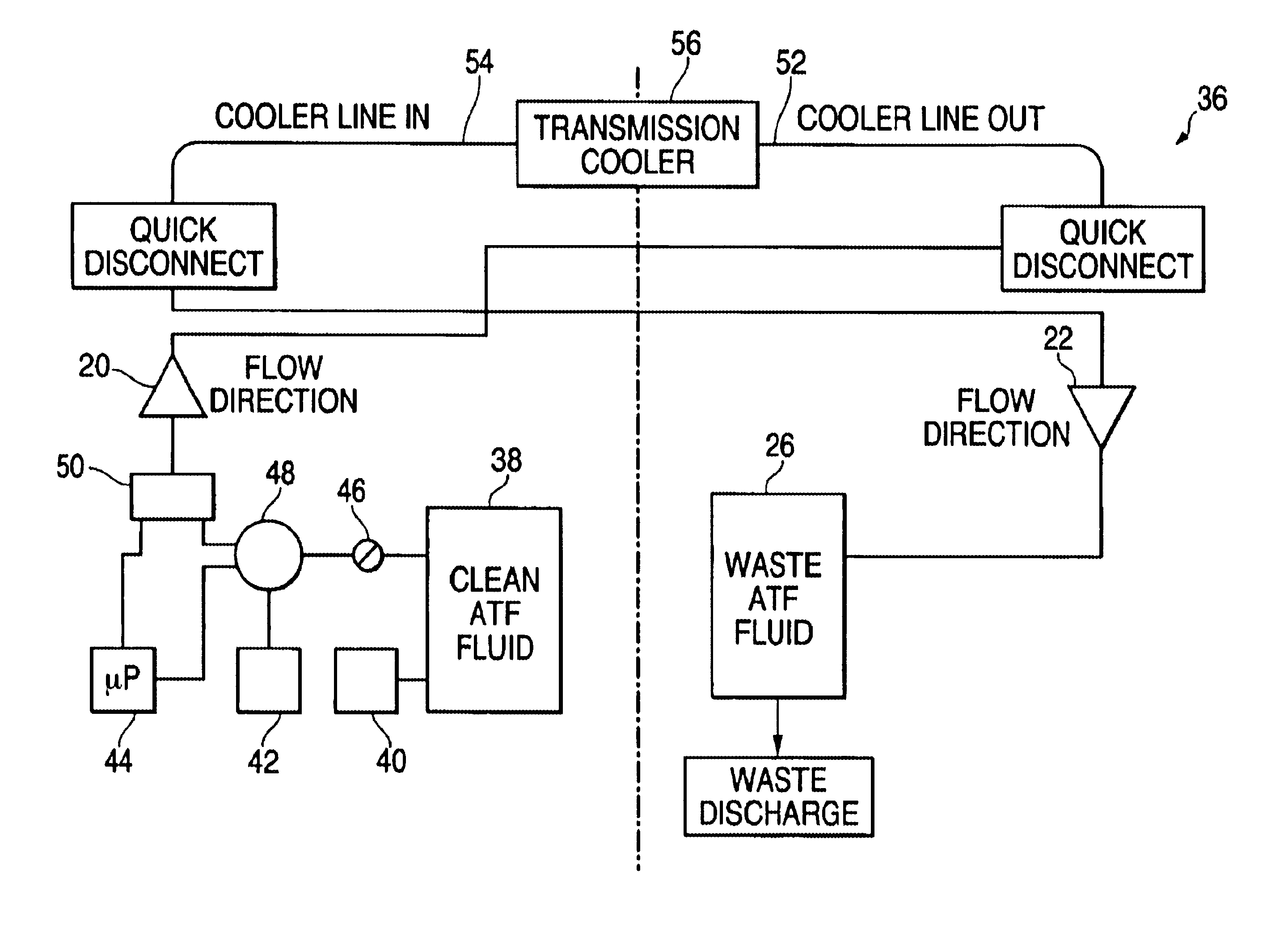
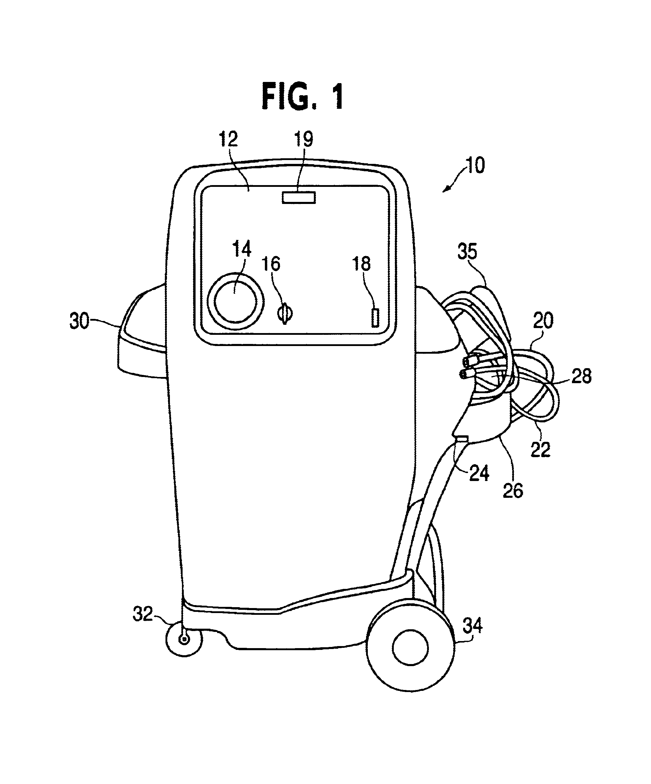
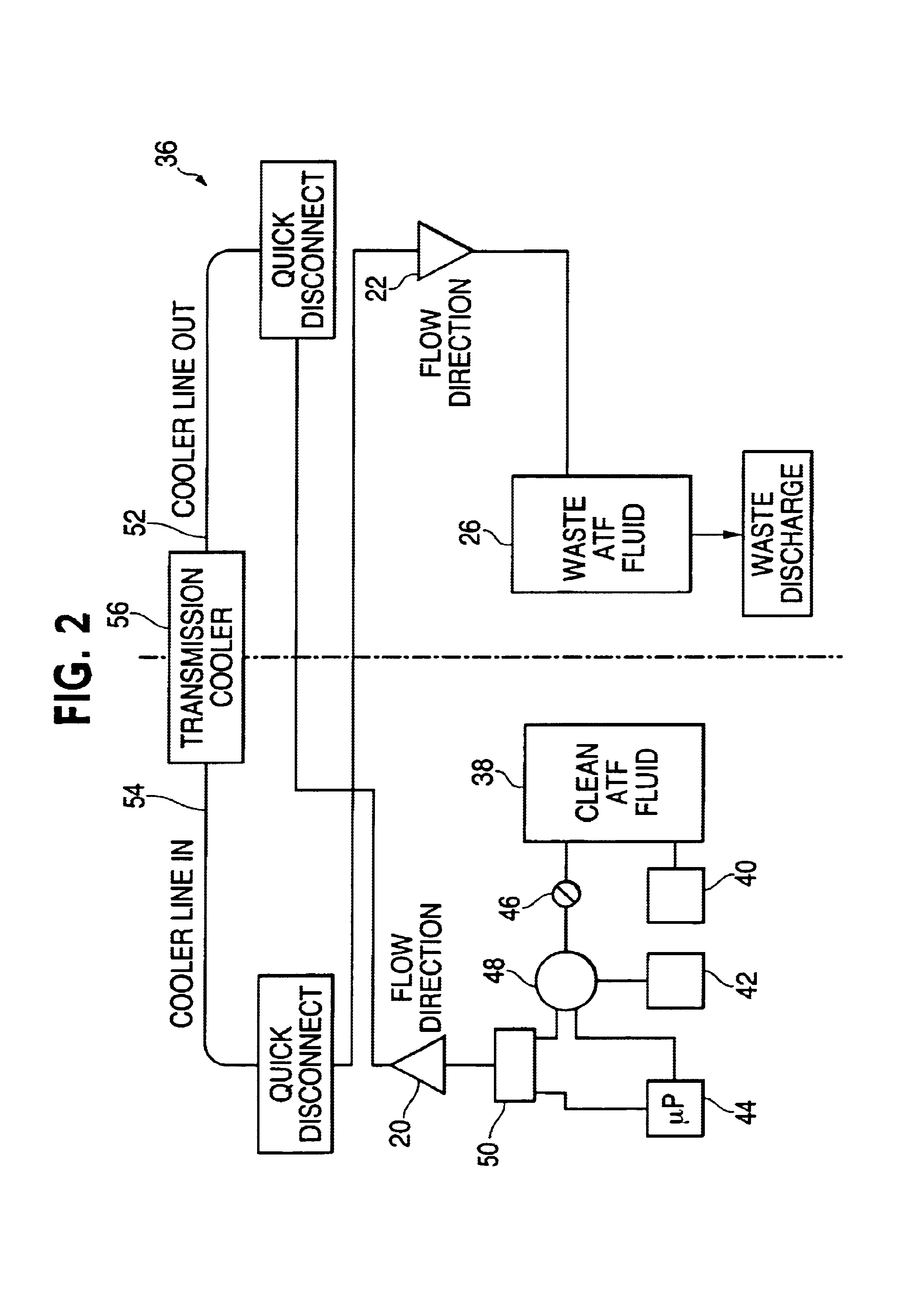
The present invention provides an apparatus, as depicted in FIG. 1, for testing flow to a cooling system and / or a transmission, flushing the cooling system or exchanging transmission fluid. The device 10 is preferably comprised of a stamp steel skeleton with a plastic exterior shell. The interface 12 allows an operator to set the device for performing a variety of functions by selecting an operating mode. The selected mode allows the device to perform one of either a fluid flow testing operation, a cooling system flushing operation, or a fluid exchange operation.

In the flow testing mode, the apparatus acts as a flow diagnostic machine by determining whether fluid flowing from an independent source is properly flowing through a cooling system. In the flushing mode, the apparatus provides turbulence to the fluid flow and performs a flushing operation. In the exchange mode, the apparatus compares flow entering and leaving a transmission and adjusts the rate of flow accordingly as it si...


PUM


Abstract

Method and apparatus provided to accurately test flow and flush cooling systems.

Description

FIELD OF THE INVENTIONThe present invention relates generally to the field of flushing cooling systems. More particularly, the present invention relates to a method for testing fluid flow and flushing transmission cooling systems and a transmission cooling system flow tester device.BACKGROUND OF THE INVENTIONMany consumer and industrial vehicles use automatic transmissions filled with automatic transmission fluid (ATF) as the working fluid and to aid in cooling the transmission. In typical configurations, automatic transmissions are equipped with a cooling system, such as an oil cooler, that may be located, for instance, inside an automobile radiator. The automatic transmission fluid is cycled through the oil cooler to regulate its temperature and then back into the transmission in order to keep the transmission cool.The importance of maintaining fresh and clean transmission fluid is essential in keeping the transmission cool. At regular intervals, the automatic transmission fluid s...

Claims


Application Information

Patent Timeline
IPC IPC(8): F01P11/14F01P11/00F01P11/06
CPCF01P11/06F01P11/14F16H57/0408F01P2031/00F01P2060/045F01P2011/065
Inventor MILLS, RICHARDMURRAY, WALTERPOPOFF, DANIEL J.
Owner SPX CORP
Why Eureka
Try Eureka