
Compression fitting nut with interlocked ferrule

a technology of compression fittings and ferrules, which is applied in the field of compression fittings, can solve the problems reducing the number of materials available, weakening or destroying the assembly, etc., and achieves the effect of reducing the number of parts needed to be handled, reducing the possibility of flow restriction or tubing deformation associated, and reducing the possibility of ferrule removal

Inactive Publication Date: 2008-01-08
VALCO INSTRUMENT COMPANY INC
View PDF14 Cites 49 Cited by
  • Summary
  • Abstract
  • Description
  • Claims
  • Application Information

AI Technical Summary

Benefits of technology

"The present invention is a nut and ferrule assembly that has several benefits. Firstly, it reduces the number of parts needed to be handled. Secondly, it eliminates the need for the nut to be the same material as the ferrule. Thirdly, it reduces the possibility of flow restriction or tubing deformation caused by the rotation of the ferrule. Finally, it makes it easier to remove the ferrule when needed."

Problems solved by technology

A basic problem with such system is the number of parts, namely the fitting, the ferrule, the tubing and nut.
Moreover such parts are typically small, permitting clasping by fingertips only.
Selection of an inert material sufficient in strength to serve as the nut limits the number of materials available.
Such forces may weaken or destroy the assembly.
An additional problem, distortion of the tubing, may also result from the use of such ferrule-nut assemblies.
Such forces may cause the tubing to twist relative to its opposition end or may result in deformation of the tubing end during rotation of the molded nut-ferrule assembly.
A further potential problem with the prior art nut and ferrule assembly may occur during removal of the prior art assembly from the fitting.
Due to the size of the ferrule, removal from the detail in light of such installation forces can be difficult.

Method used


Image

  • Compression fitting nut with interlocked ferrule
  • Compression fitting nut with interlocked ferrule
  • Compression fitting nut with interlocked ferrule

Examples


Embodiment Construction

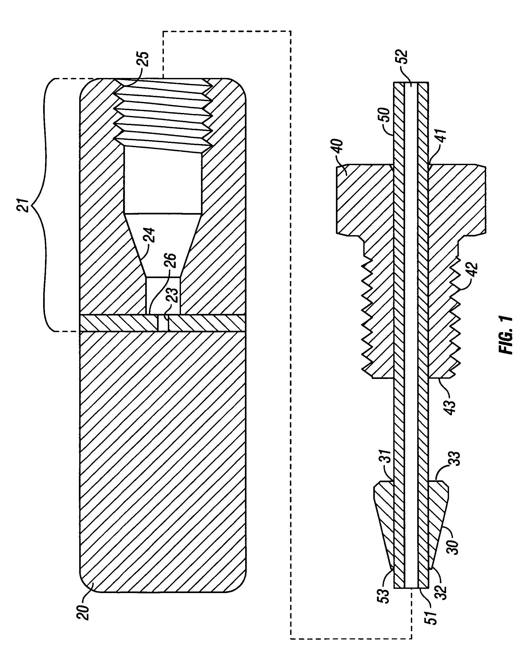
[0017]FIG. 1 depicts the prior art for a nut and ferrule assembly. Tubing 50 first passes through nut 40 at nut axial passageway 41 then through ferrule 30 at ferrule axial passageway 31, terminating in tubing end 51. Once assembled tubing end 51 abuts zero dead volume fitting detail bore bottom 26, aligning tubing 50 and tubing bore 52 with zero dead volume fitting detail bore 23. Nut 40 is then slid along tubing 50. Male threads 42 of nut 40 are then caused to engage female threads 25 of zero dead volume body fitting detail 21 which causes nut first end 43 to push ferrule 30 at ferrule second end 33. Ferrule 30 is wedge-shaped such that ferrule 30 contacts zero dead volume fitting detail ferrule seat 24. Typically an angle of 13 degrees from the axial centerline (26 degrees included) is used for the angled surface of ferrule 30 at ferrule first end 32. Typically an angle of 20 degrees from the axis centerline (40 degrees included) is used on fitting detail 21 to generate zero dead...


PUM

PropertyMeasurementUnit
angleaaaaaaaaaa
angleaaaaaaaaaa
angleaaaaaaaaaa

Abstract

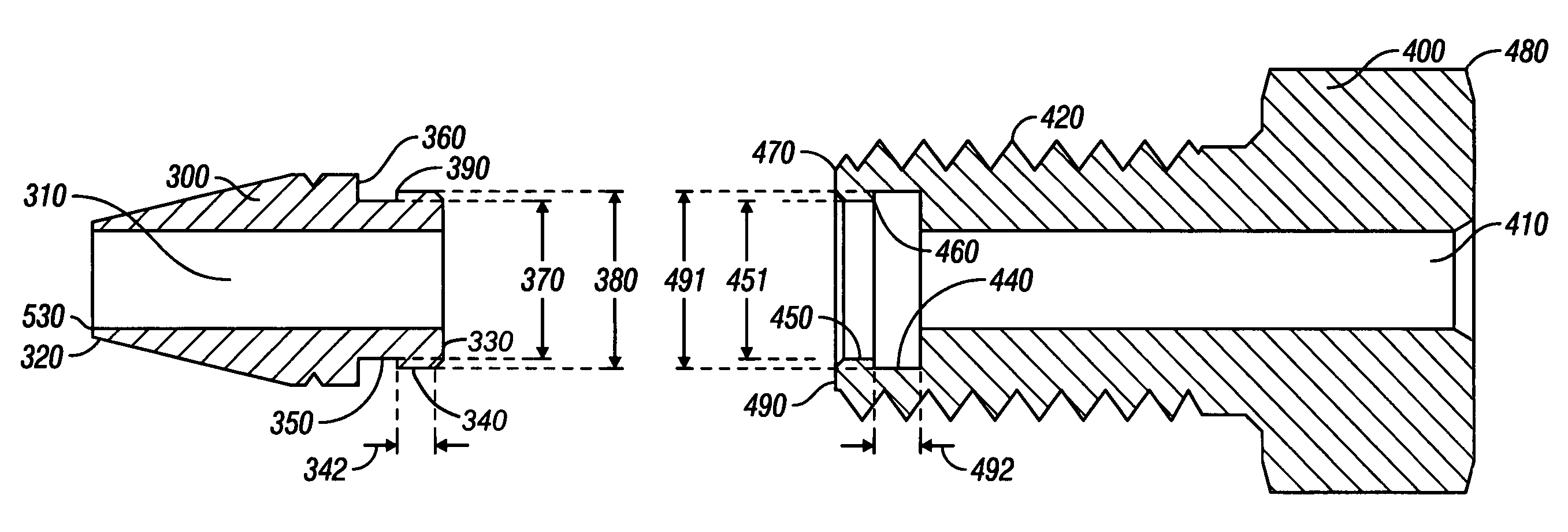
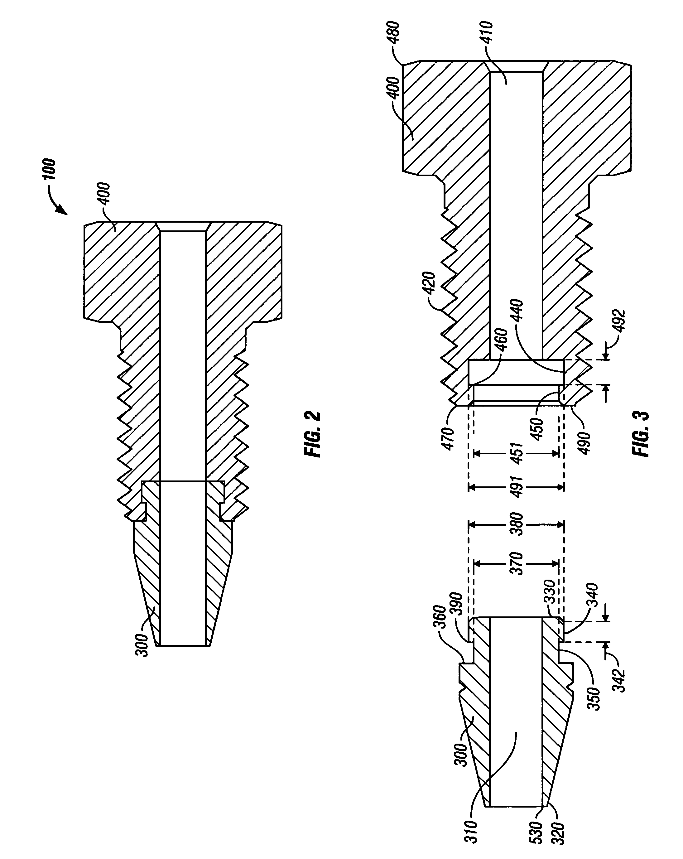
The invention pertains to a nut and ferrule assembly for use in joining tubing to a fitting. The ferrule has a male member which interlocks with a nut and freely rotates within the nut. The interlock reduces the number of parts necessary to be handled, eliminates the need for the nut to be of the same material as the ferrule, reduces the possibility of flow restriction or tubing deformation associated with rotation of the ferrule, and aids in the removal of the ferrule from the detail when removal is desired.

Description

CROSS-REFERENCE TO RELATED APPLICATIONS[0001]This application claims the benefit of U.S. Provisional Patent Application No. 60 / 648,135 entitled, “Nut with Ferrule,” filed on Jan. 28, 2005 in the United States Patent and Trademark Office.STATEMENT REGARDING FEDERALLY SPONSORED RESEARCH OR DEVELOPMENT[0002]Not Applicable.FIELD OF INVENTION[0003]This invention pertains to compression fittings for use in systems designed for chemical analysis.BACKGROUND OF THE INVENTION[0004]It is necessary in analytical systems to have fittings that create leak-tight seals. In such analytical systems, it is also desirous to have fittings which are inert relative to the sample components, which provide a flow path without inducing turbulence or mixing, and which adds minimal volume to the system.[0005]Fitting designs which best address the aspect of added volume allow the tube ends which pass through such fittings to butt directly to each other or have bores which match the tubing bore, leaving no dead ...

Claims


Application Information

Patent Timeline
Patent Type & Authority Patents(United States)
IPC IPC(8): B01D15/08
CPCB01L3/565G01N30/6004G01N30/6039
Inventor LOY, JR., H. MAX
Owner VALCO INSTRUMENT COMPANY INC
Learn More