
Optimization of manufacturing equipment capacities in a batch manufacturing process

a manufacturing equipment and batch technology, applied in the direction of total factory control, programme control, instruments, etc., can solve the problems of short bcd, oversizing and/or underutilization of equipment in batch processes, and the schedule of equipment utilization in these batch processes is complex, so as to minimize equipment and direct utility costs, minimize equipment utilization, and minimize the effect of cost of goods

Inactive Publication Date: 2005-03-08
BROWN OWEN (I) (US)
View PDF2 Cites 22 Cited by
  • Summary
  • Abstract
  • Description
  • Claims
  • Application Information

AI Technical Summary

Benefits of technology

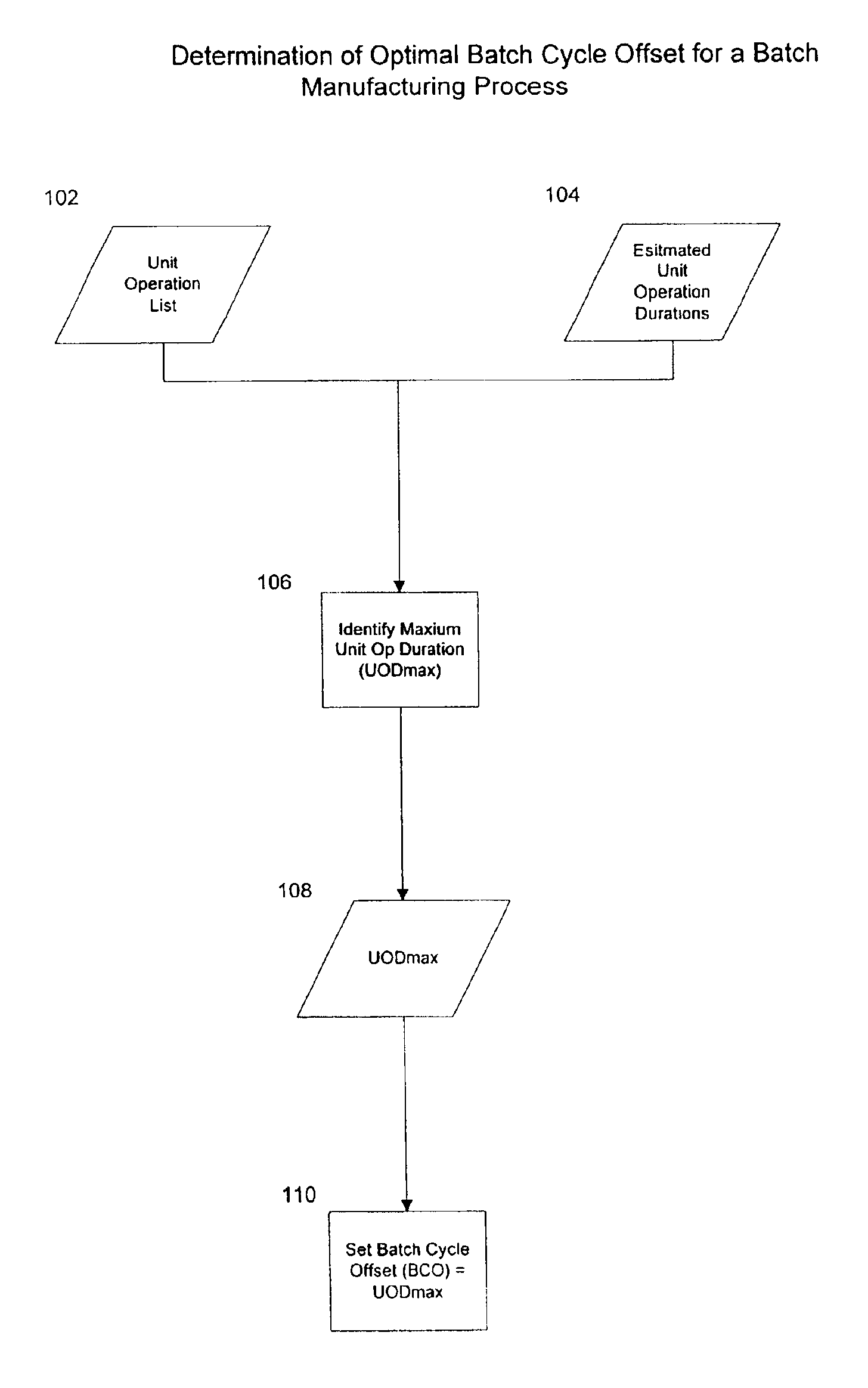
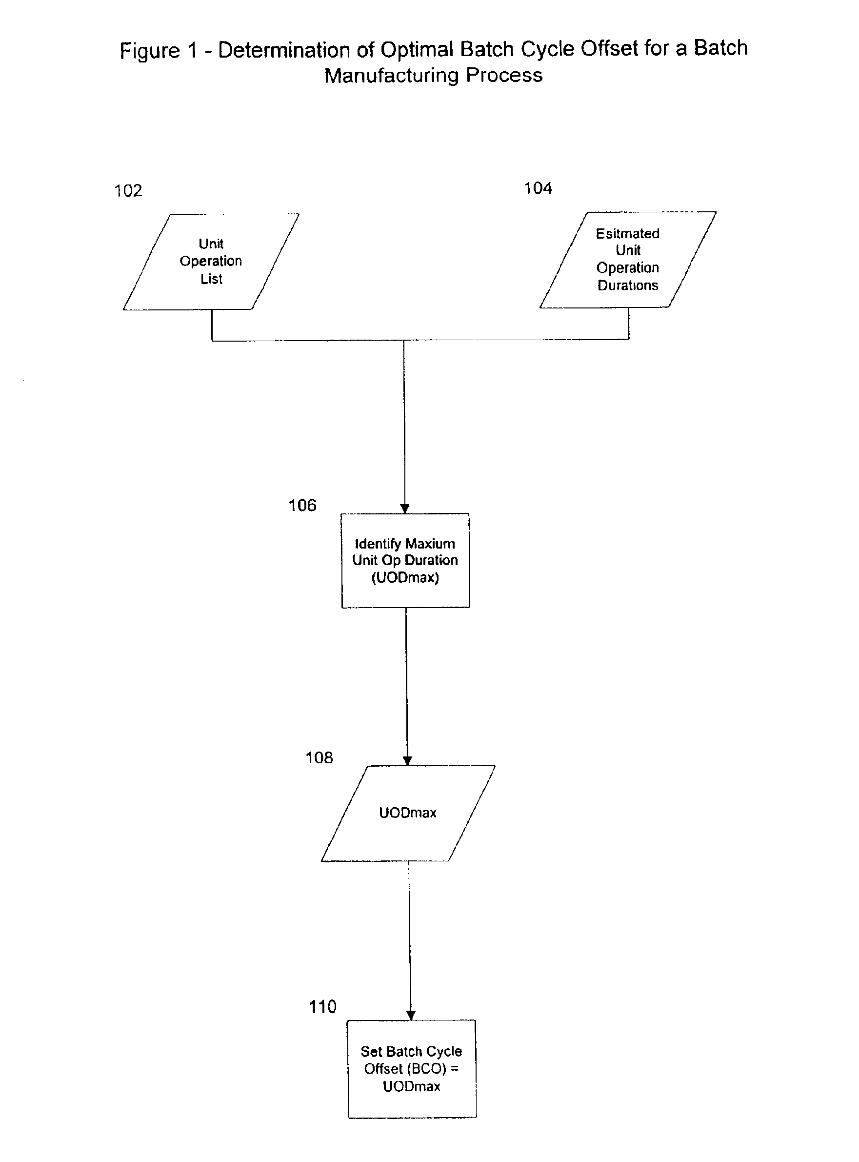
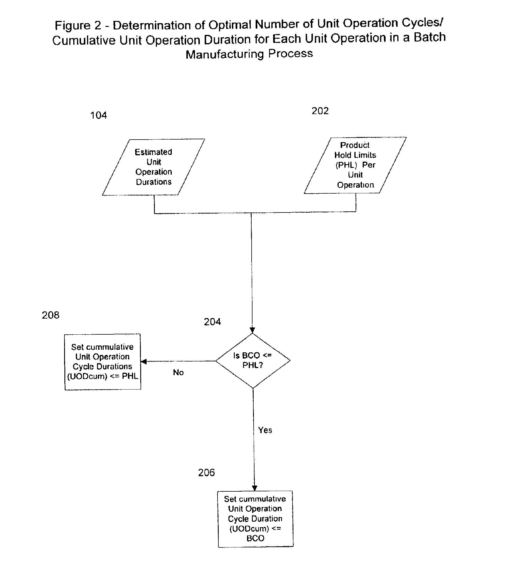
In an effort to achieve the lowest cost of goods (COG) possible, a key objective in batch manufacturing is to maximize equipment utilization so that the capacity and size of equipment per batch cycle is the smallest possible for a given batch production capacity. This optimization of equipment utilization minimizes equipment and direct utility costs per batch, as well as reduces the physical space and the associated utilities required to support manufacturing operations. The present invention provides a means of: (1) determining the optimal number of batch cycles per year for a required annual production capacity; and (2) determining the optimal number of equipment cycle iterations per batch cycle in a manner that: (a) creates the smallest batch sizes possible; and (b) achieves higher equipment utilization per batch cycle, thereby reducing the capacity and size of equipment required to produce a given batch quantity of product.

Problems solved by technology

The scheduling of equipment utilization in these batch processes tends to be complex relative to other industries that use continuous or repetitive manufacturing procedures.
This complexity often results in an oversizing and / or underutilization of equipment in batch processes to meet a required production capacity per batch cycle due to a general lack of well-defined rules for batch process scheduling.
Often, however a short BCD is required due to the instability of the product.
These practices, however, fail to define an optimal relationship between these cycles and the BCO that both maximizes the number of theoretical batches per year for a given production quantity and maximizes the number of equipment cycles per batch.
As a result, these conventional practices do not allow for optimal equipment utilization and lowest cost of goods (COG) for batch manufacturing.

Method used


Image

  • Optimization of manufacturing equipment capacities in a batch manufacturing process
  • Optimization of manufacturing equipment capacities in a batch manufacturing process
  • Optimization of manufacturing equipment capacities in a batch manufacturing process

Examples


Embodiment Construction

When appropriate emphasis is placed on achieving an optimal process design that produces the lowest COG, minimizing batch equipment capacities for a given annual production requirement (APR) becomes a focus of attention. As a first step, this minimization of batch equipment capacities is achieved by determining the optimal BCO for each batch cycle. As a second step, this minimization of batch equipment capacities is achieved by distributing the APR over the maximum possible number of batches per year based upon the optimal BCO and in a manner that takes into account the loss of available manufacturing time due to plant shut downs, equipment maintenance and equipment turnaround times. As a third step, the minimization of batch equipment capacities is achieved by cycling the equipment associated with each given unit operation the maximum number cycles possible per batch cycle in order to achieve high equipment utilization factors that minimize the size of equipment for a given batch c...


PUM


Abstract

In an effort to achieve the lowest cost of goods (COG) possible, a key objective in batch manufacturing is to maximize equipment utilization so that the capacity and size of equipment per batch cycle is the smallest possible for a given batch production capacity. This optimization of equipment utilization minimizes equipment and direct utility costs per batch, as well as reduces the physical space and the associated utilities required to support manufacturing operations. The present invention provides a process of: (1) determining the optimal number of batch cycles per year for a required annual production capacity; and (2) determining the optimal number of equipment cycle iterations per batch cycle in a manner that: (a) creates the smallest batch sizes possible; and (b) achieves higher equipment utilization per batch cycle, thereby reducing the capacity and size of equipment required to produce a given batch quantity of product.

Description

BACKGROUND OF THE INVENTION1. Field of the InventionThe present invention relates generally to large scale batch manufacturing facilities, and more specifically to the optimization within such facilities.2. Related ArtBatch manufacturing is a dominant method of producing a number of valuable products such as food, beverages, specialty chemicals, pharmaceuticals, etc. An overview of the biopharmaceutical production process and its associated plant design, for example, can be found in U.S. Pat. No. 6,311,095, issued Oct. 30, 2001 and U.S. patent application Ser. No. 09 / 373,793, filed Aug. 13, 1999, both having common inventorship and are hereby incorporated by reference in their entireties.The scheduling of equipment utilization in these batch processes tends to be complex relative to other industries that use continuous or repetitive manufacturing procedures. This complexity often results in an oversizing and / or underutilization of equipment in batch processes to meet a required prod...

Claims


Application Information

Patent Timeline
IPC IPC(8): G05B19/418G06Q10/00G06Q10/04
CPCG05B19/41865G06Q10/04G05B2219/32283G05B2219/32304G05B2219/32293Y02P90/02
Inventor BROWN, PETER G.
Owner BROWN OWEN (I) (US)
Learn More