
Low noise resistorless band gap reference

a resistorless, low-noise technology, applied in the direction of electric variable regulation, process and machine control, instruments, etc., can solve the problems of increasing cost, increasing the cost of each differential amplifier, and requiring physically large switches, so as to achieve the effect of easy acquisition of low temperature coefficient current sources

Inactive Publication Date: 2005-03-08
MARSH DOUGLAS G +1
View PDF12 Cites 17 Cited by
  • Summary
  • Abstract
  • Description
  • Claims
  • Application Information

AI Technical Summary

Benefits of technology

"The invention is about a new design for a reference voltage that is used in electronic circuits. The design uses a special arrangement of junctions in bipolar transistors to achieve a reference voltage that is stable over temperature. This is done by controlling the number of junctions and the current densities. The design requires only one polarity of transistors, which reduces noise and makes it easier to get a low temperature coefficient current source. This design also avoids the need for resistors and simplifies the process of creating a stable reference voltage."

Problems solved by technology

However, this design requires both PNP and NPN transistors.
To obtain an NPN transistor, a BiCMOS process is typically used, increasing cost.
Each differential amplifier adds to the die area and to the total noise.
This requires physically large switches, using considerable die area.

Method used


Image

  • Low noise resistorless band gap reference
  • Low noise resistorless band gap reference
  • Low noise resistorless band gap reference

Examples


Embodiment Construction

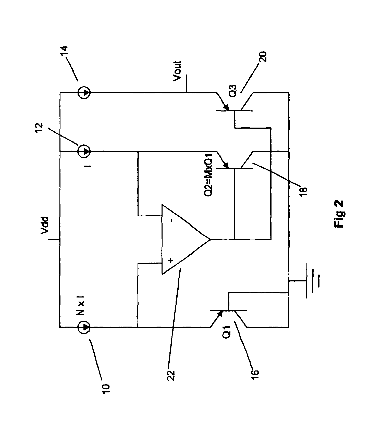
The basic concept of the invention is shown in FIG. 2. A first current source 10 is N times bigger than a second current source 12. A first bipolar transistor Q116 and a second bipolar transistor Q218 are in a 1:M size ratio. The result is that the current density in the first bipolar transistor 16 will be N×M larger than in the second bipolar transistor 18. Those skilled in the art will immediately recognize that amplifier 22 forces the emitters of transistor 16 and transistor 18 to be at essentially equal potentials with respect to the base of transistor 16, shown here connected to ground. This forces the base of the transistor 18 to be approximately (kT / q)×ln(N×M) volts higher than the base of the transistor 16. Therefore, the output voltage will be the combination of this voltage added to the base-emitter voltage of a third bipolar transistor Q320 which is biased from a third current source 14.

Vout=Vbe(Q3)+(kT / q)×ln(N×M)

It is well known that the base-emitter voltage of transist...


PUM


Abstract

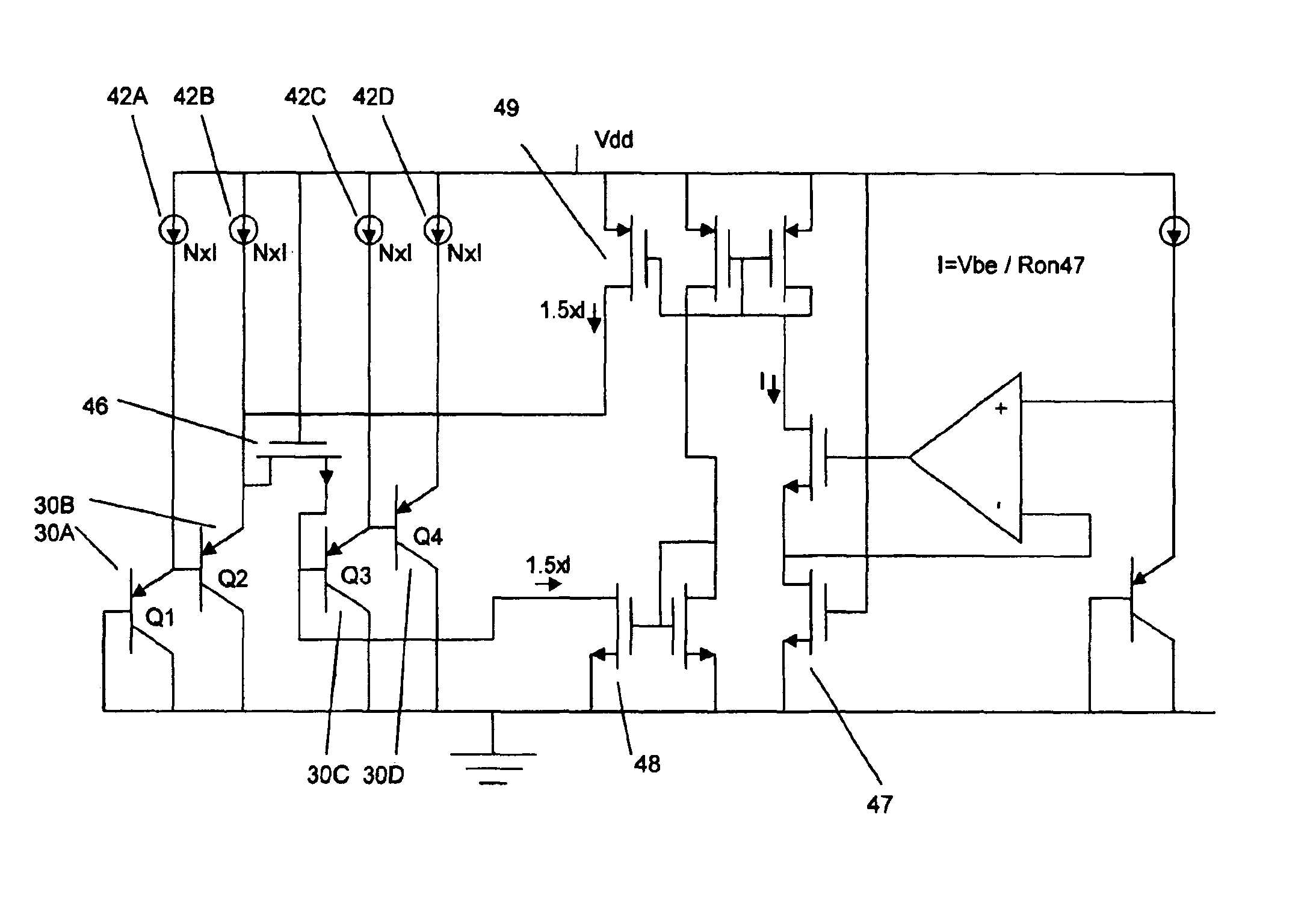
The junction difference used for a band gap voltage reference is designed so that it has the needed temperature coefficient without amplification. This is accomplished by the appropriate choice of the number of junctions and the appropriate current densities. Only one polarity of bipolar transistors is required. The noise terms of each junction add in root mean square, rather than be linear amplification, resulting in a lower noise reference than other designs requiring only a single type of bipolar transistors. By using metal available in standard integrated circuit processes to form a resistor, a low temperature coefficient current source can easily be obtained.

Description

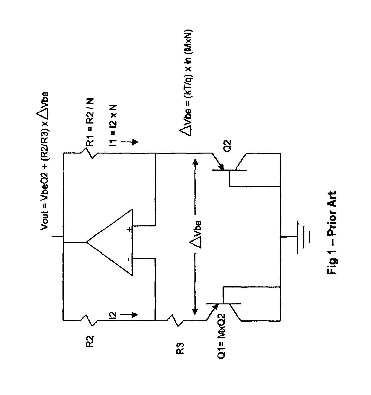
CROSS-REFERENCE TO RELATED APPLICATIONSNot applicable.BACKGROUND1. Field of InventionThis invention relates to integrated circuit band gap reference sources, specifically, to a design that requires only one polarity of bipolar transistor and does not require any resistors.2. Description of Prior ArtNumerous patents have been issued for band gap reference voltages, the most basic implementation of which is shown in FIG. 1. This design is well known and will be reviewed here only very briefly. In designs of this type, a differential base-emitter voltage drop is generated across a pair of bipolar junctions, and this difference is amplified by a resistor ratio. The resultant voltage has a positive temperature coefficient. This resultant voltage is then added to a junction voltage, which has a negative temperature voltage. By well known means the positive temperature coefficient is set to equal the negative temperature coefficient, and the result is a voltage with very small temperature ...

Claims


Application Information

Patent Timeline
Patent Type & Authority Patents(United States)
IPC IPC(8): G05F3/08G05F3/30
CPCG05F3/30
Inventor MARSH, DOUGLAS G.GANESAN, APPARAJAN
Owner MARSH DOUGLAS G
Learn More