
Matrix type actuator

a piezoelectric/electrostrictive, matrix-type technology, applied in the direction of generator/motor, device details, device details, etc., can solve the problems of reducing power loss, difficult to increase the magnitude of generated stress, and difficult to increase the responsive speed satisfactorily

Inactive Publication Date: 2005-03-08
NGK INSULATORS LTD
View PDF15 Cites 36 Cited by
  • Summary
  • Abstract
  • Description
  • Claims
  • Application Information

AI Technical Summary

Benefits of technology

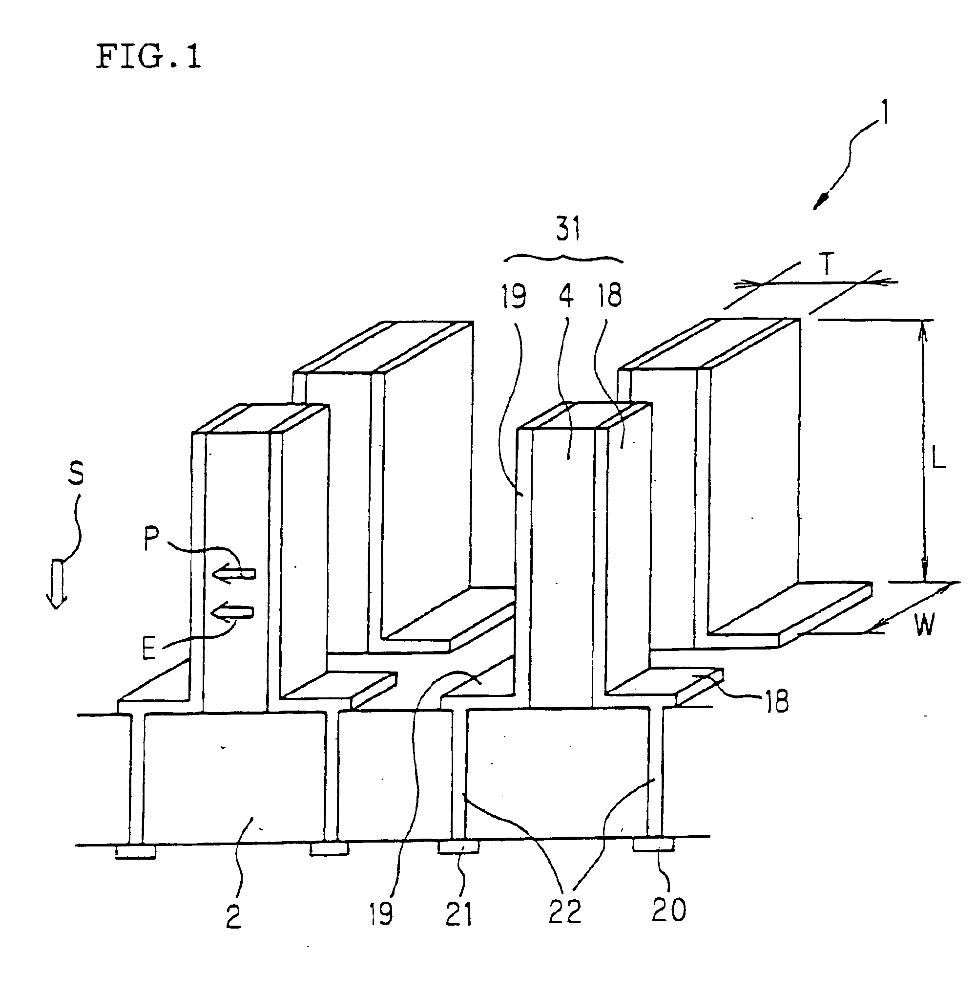
The actuator according to the present invention, in particular, comprises two types of actuators. A first matrix type P / E actuator according to the present invention is an actuator in which the piezoelectric / electrostrictive element is formed by disposing piezoelectric / electrostrictive body vertically on the ceramic substrate and the electrodes are formed on the side surfaces of said body. More preferably, the electrodes are formed on the side surfaces including the long side of the cross section of the piezoelectric / electrostrictive body, in such a manner that said cross section of the piezoelectric / electrostrictive body in the piezoelectric / electrostrictive element shows a parallelogram shape in the cross section parallel direction to the substrate. In the first matrix type P / E actuator, it is desirable that the piezoelectric / electrostrictive elements are expanded / contracted in the vertical direction to the main surface of said ceramic substrate due to the transverse effect of the electric field induced strain. Moreover, it is preferable that the condition of crystal grains in the wall surfaces of the piezoelectric / electrostrictive bodies of the piezoelectric / electrostrictive elements, where the electrodes is formed on the wall surfaces, is that the crystal grains suffering the transgranular fracture inside the grain are 1% or less, and it is preferable that the degree of profile for the surfaces of the piezoelectric / electrostrictive bodies in the piezoelectric / electrostrictive elements is approximately 8 μm or less. It is also preferable that the surface roughness Rt of the wall surfaces of the piezoelectric / electrostrictive bodies in the piezoelectric / electrostrictive element is approximately 10 μm or less.
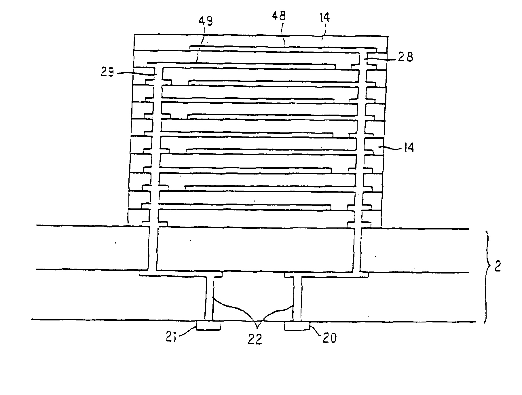
The second matrix type P / E actuator according to the present invention is an actuator according wherein the piezoelectric / electrostrictive elements are formed on the ceramic substrate by alternately interleaving stratiform piezoelectric / electrostrictive bodies into stratiform electrodes. In the second matrix type P / E actuator, it is preferable that the piezoelectric / electrostrictive elements are expanded / contracted in the vertical direction to the main surface of the ceramic substrate due to the longitudinal effect of the electric field induced strain. And it is preferable that the thickness of one layer of the piezoelectric / electrostrictive body in the piezoelectric / electrostrictive elements is 100 μm or less. It is also preferable that the number of layers forming said piezoelectric / electrostrictive body in the piezoelectric / electrostrictive elements is 10 to 200.

Problems solved by technology

However, since the strain was converted in such a way, the stress arising directly from the strain of the piezoelectric / electrostrictive elements could not be directly used, and therefore it was very difficult to increase the magnitude of the generated stress.
Moreover, it was also difficult to increase the responsive speed satisfactorily, since the resonance frequency inevitably decreased with the increase of the length of the elements.
Secondly, there is a requirement of reducing the power loss due to the switching.
Since, however, such an increase in the contact area causes a reduction in the reliability of separation, an actuator generating a greater force is necessary.
Nevertheless, it was difficult to obtain a greater amount of displacement with a smaller applied voltage, since the distance between the electrodes is large.
Moreover, the piezoelectric element disclosed in JP-A-60-90770 is produced by processing the resultant with cutting using diamond saw, and therefore there is a problem in that the element is not free from damages inherently formed by the machining.

Method used


Image

  • Matrix type actuator
  • Matrix type actuator
  • Matrix type actuator

Examples


Embodiment Construction

In the following, various embodiments for the matrix type P / E actuator according to the present invention will be concretely described. However, the present invention is not restricted to these embodiments, and various alterations, revisions and modifications are possible without departing from the scope of the present invention. Here, the matrix type P / E actuator according to the present invention belongs to a piezoelectric / electrostrictive actuator, and therefore it is an actuator in which an electric field induced strain is utilized. However, the matrix type P / E actuator is not restricted to an actuator in which the piezoelectric effect of generating a strain substantially proportional to an applied electric field or the electro-strictive effect of generating a strain substantially proportional to the square of an applied electric field is utilized in a narrow sense, but it also includes an actuator in which a phenomenon of a polarization reversal found in ferroelectric materials...


PUM

PropertyMeasurementUnit
surface roughnessaaaaaaaaaa
thicknessaaaaaaaaaa
displacementaaaaaaaaaa

Abstract

A matrix type piezoelectric / electrostrictive (PIE) actuator includes a plurality of piezoelectric / electrostrictive elements, each including a piezoelectric / electrostrictive body and at least one pair of electrodes formed on a ceramic substrate. The matrix type P / E actuator is activated by displacement of the piezoelectric / electrostrictive bodies. The piezoelectric / electrostrictive elements are joined to the ceramic substrate as respective unified bodies, and are two-dimensionally arranged independently from each other. The piezoelectric / electrostrictive actuator provides a greater displacement with a lower voltage, a high responsive speed, and a greater generating force, as well as enhancing the mounting ability and the integration. A method for manufacturing such a matrix type P / E actuator is also disclosed.

Description

BACKGROUND OF THE INVENTION AND RELATED ARTThe present invention relates to a matrix type piezoelectric / electrostrictive (P / E) actuator, more specifically, to a matrix type PE actuator which may be used in an optical modulator, an optical switch, an electric switch, a micro relay, micro valve, a conveyor apparatus, an image display apparatus such as a display, a project or, and the like, an image drawing apparatus, a micro pump, a droplet ejecting apparatus, a micro mixing apparatus, a micro stirring apparatus, a micro reactor, and the like. The matrix type P / E actuator is provided with a higher generating force and a greater displacement; and preferably is capable of showing such a function to objectives as pressing, deforming, moving, hammering (giving an impact), mixing, or the like by expressing expansion / contraction displacement and / or vibration in a direction perpendicular to the main surface of a ceramic substrate owing to transverse effect of the electric field induced strai...

Claims


Application Information

Patent Timeline
Patent Type & Authority Patents(United States)
IPC IPC(8): H01L41/00H01L41/04H01L41/08H01L27/20H01L41/24H04R17/00H05K3/36
CPCB41J2/14209H01L27/20H01L41/339H01L41/338H02N2/021Y10T29/4913Y10T29/435Y10T29/43Y10T29/49078Y10T29/42Y10T29/49126Y10T29/49833H10N39/00H10N30/089H10N30/088
Inventor TAKEUCHI, YUKIHISATSUJI, HIROYUKIKITAMURA, KAZUMASATAKAHASHI, NOBUOKIMURA, KOJI
Owner NGK INSULATORS LTD
Learn More