Eureka AIR delivers breakthrough ideas for toughest innovation challenges, trusted by R&D personnel around the world.

Laser-air, hybrid, ultrasonic testing of railroad wheels

a technology of ultrasonic testing and rail wheels, applied in the direction of analysing solids using sonic/ultrasonic/infrasonic waves, instruments, transportation and packaging, etc., can solve the problems of rail road maintenance, negative influence on the amount of light reflecting back to the optical detector, and the efficiency of the light reflected

Inactive Publication Date: 2005-03-08
THE JOHN HOPKINS UNIV SCHOOL OF MEDICINE
View PDF18 Cites 59 Cited by
  • Summary
  • Abstract
  • Description
  • Claims
  • Application Information

AI Technical Summary

Benefits of technology

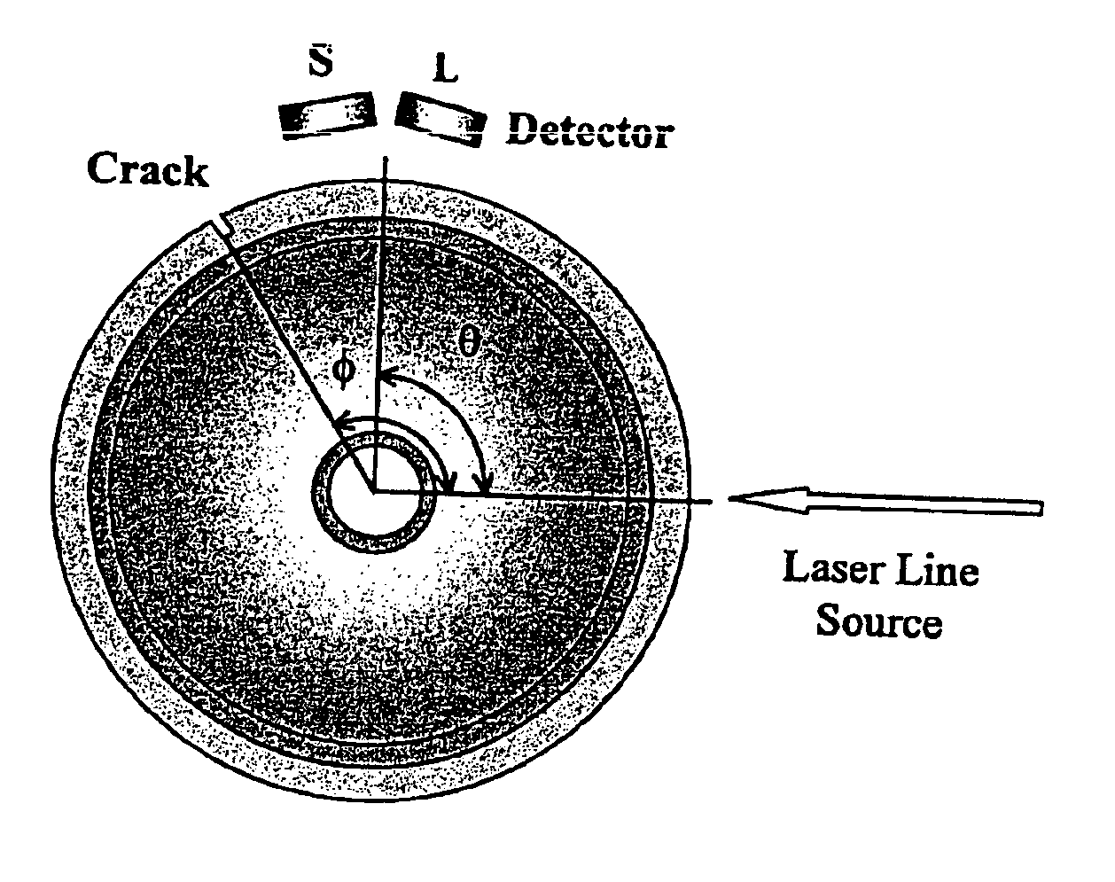
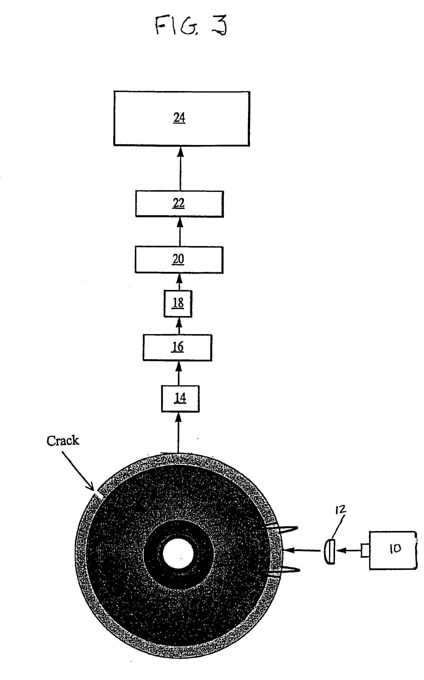
The present invention is about a system and method for detecting flaws in railroad wheels while they are stationary or moving along a railroad track. The system includes a laser light source, optical components, an air-coupled transducer, and a signal processor. The laser light source generates an ultrasonic wave in the wheel body, which is then sensed by the transducer. The signal processor analyzes the sensed acoustic signal to detect any reflected portions, which indicates the presence of a defect in the surface of the railroad wheel. The technical effects of this invention include the ability to detect both surface breaking and internal anomalies in railroad wheels using advanced signal analysis methods.

Problems solved by technology

Railroad maintenance is one of the greatest problems facing the transportation industry today.
However, their efficiency relies heavily on the amount of light reflected back from the surface.
As a result, the curvature, roughness and cleanliness of the reflecting surface all have a negative influence on the amount of light reflecting back to the optical detector.
This, unfortunately, renders these techniques ineffective for many industrial applications, including the railroad industry.
Other than by visual inspection, no technique is readily available today to the railroad industry to perform inspections on railroad wheels while they are still mounted on a train.
Prior acoustic inspection techniques have proved to be unreliable.
However, both the generating technique and the detecting transducer operated with low frequency sound, such that the signal was often indistinguishable from mechanical noise.

Method used


Image

  • Laser-air, hybrid, ultrasonic testing of railroad wheels
  • Laser-air, hybrid, ultrasonic testing of railroad wheels
  • Laser-air, hybrid, ultrasonic testing of railroad wheels

Examples


Embodiment Construction

n so that it is embedded in the rail track on which the to-be-inspected wheel is to move.

[0042]FIG. 15 illustrates schematically a scheme for orienting the detector of the present invention so that it is in a protective housing that faces an opening made in the rail track to guide the acoustic signal to the detector.

[0043]FIG. 16 illustrates schematically a scheme for orienting the detector of the present invention in a manner similar to that shown in FIG. 15 but where the opening in the rail track has been machined to focus the acoustic signal at the detector.

[0044]FIG. 17 illustrates schematically a scheme for orienting the detector of the present invention so that it is in a protective housing that faces an ultrasound mirror dimple made in the rail track so that the signal propagating along the surface of the rail wheel reflects from the dimple on the rail and arrives at the detector which is positioned safely outside the wheel path.

[0045]FIG. 18 illustrates schematically a schem...


PUM

PropertyMeasurementUnit
frequenciesaaaaaaaaaa
liftoff distancesaaaaaaaaaa

Abstract

A remote, non-contact system for detecting a defect in a railroad wheel as the wheel is stationary or moving along a railroad track includes; (1) a pulsed, laser light source for generating an ultrasonic wave in the wheel, the ultrasonic wave having a direct portion and reflected and transmitted portions if the direct portion encounters a defect in the wheel, (2) an optical component in the path of the light from the light source for forming the light into a specified illumination pattern so that the generated ultrasonic wave has a specified wavefront, (3) an air-coupled transducer or a group of transducers for sensing the acoustic signal emanating from the wheel that results from the ultrasonic wave traveling through the wheel, and (4) a signal processor, responsive to the sensed acoustic signal, capable of distinguishing whether the sensed signal has a component that indicates the existence of a reflected portion in the ultrasonic wave, wherein the presence of such a component in the acoustic signal indicates the existence of a defect in the railroad wheel.

Description

CROSS-REFERENCE TO RELATED APPLICATION[0002]This application claims the benefit of U.S. Provisional Patent Application No. 60 / 429,981, filed Nov. 27, 2002 by Shant Kenderian, B. Boro Djordjevic and Donatella Cerniglia.BACKGROUND OF THE INVENTION[0003]1. Field of the Invention[0004]This invention relates to non-contact remote ultrasonic testing of railroad wheels. More particularly, this invention relates to a method for using a Laser-Air Hybrid Ultrasonic Technique (LAHUT) as a noncontact and remote ultrasonic system for testing railroad wheels.[0005]2. Description of the Related Art[0006]Railroad maintenance is one of the greatest problems facing the transportation industry today. In one four-month period in 1998, a major railroad company experienced ten derailments due to broken rail at an expense of over $1.3 million. In its Newsletter, in Sep. of 2000, the Texas Research Institute estimated that every ninety minutes a derailment, an accident, or any other rail related incident t...

Claims


Application Information

Patent Timeline
Patent Type & Authority Patents(United States)
IPC IPC(8): G01M17/08G01M17/10
CPCG01M17/10G01N2291/2696G01N2291/044
Inventor KENDERIAN, SHANTDJORDJEVIC, B. BOROCERNIGLIA, DONATELLA
Owner THE JOHN HOPKINS UNIV SCHOOL OF MEDICINE
Why Eureka
Eureka Blog
Learn More