
Reinforcing bar coupling

a technology of reinforcing bars and couplings, applied in the field of couplings, can solve the problems of increasing the number of reinforcing bars, difficulty in pouring concrete into space, and difficulty in reinforcing bars, and achieves the effects of convenient and firm coupling, avoiding excessive consumption of reinforcing bars, and advantageous cost saving

Inactive Publication Date: 2005-03-01
KIM EE
View PDF8 Cites 21 Cited by
  • Summary
  • Abstract
  • Description
  • Claims
  • Application Information

AI Technical Summary

Benefits of technology

Accordingly, the present invention has been made keeping in mind the above problems occurring in the prior art, and an object of the present invention is to provide a reinforcing bar coupling which is capable of achieving a firm joining between reinforcing bars by a simple operation of inserting wedges between the reinforcing bars and a cylindrical sleeve and hammering the wedges.
The reinforcing bar coupling according to the present invention can be commonly used in joining two reinforcing bars in new construction, rebuilding and repair work of various concrete structures such as bridges and buildings. The reinforcing bar coupling enables easy and firm coupling of reinforcing bars using only a simple striking tool. Furthermore, since reinforcing bars are coupled to each other without overlapping thereof, excessive consumption of reinforcing bars can be prevented and advantageous cost savings can be achieved. In addition, the reinforcing bar coupling exhibits superior bonding strength compared to a conventional coupling method.

Problems solved by technology

However, the lap-joint process has disadvantages in that distances between the adjacent reinforcing bars become small at the lapped regions, the required number of reinforcing bars is increased due to the lapped regions of the reinforcing bars, a pouring operation of concrete into space between the lapped reinforcing bars is difficult due to the small distances between the adjacent reinforcing bars, and the lap-jointed reinforcing bars are weakened in resistance to axial tensile force and compressive force.
However, the above thread-joint process also has disadvantages in that it requires many working steps to form male threads on the ends of the reinforcing bars, and although reinforcing bars are considerably long and apt to be bent due to the material characteristics thereof, two reinforcing bars must be precisely aligned with each other to allow the ends of the reinforcing bars to be threaded into a coupling, thereby involving inconvenience in the joining operation.

Method used


Image

  • Reinforcing bar coupling
  • Reinforcing bar coupling
  • Reinforcing bar coupling

Examples


first embodiment

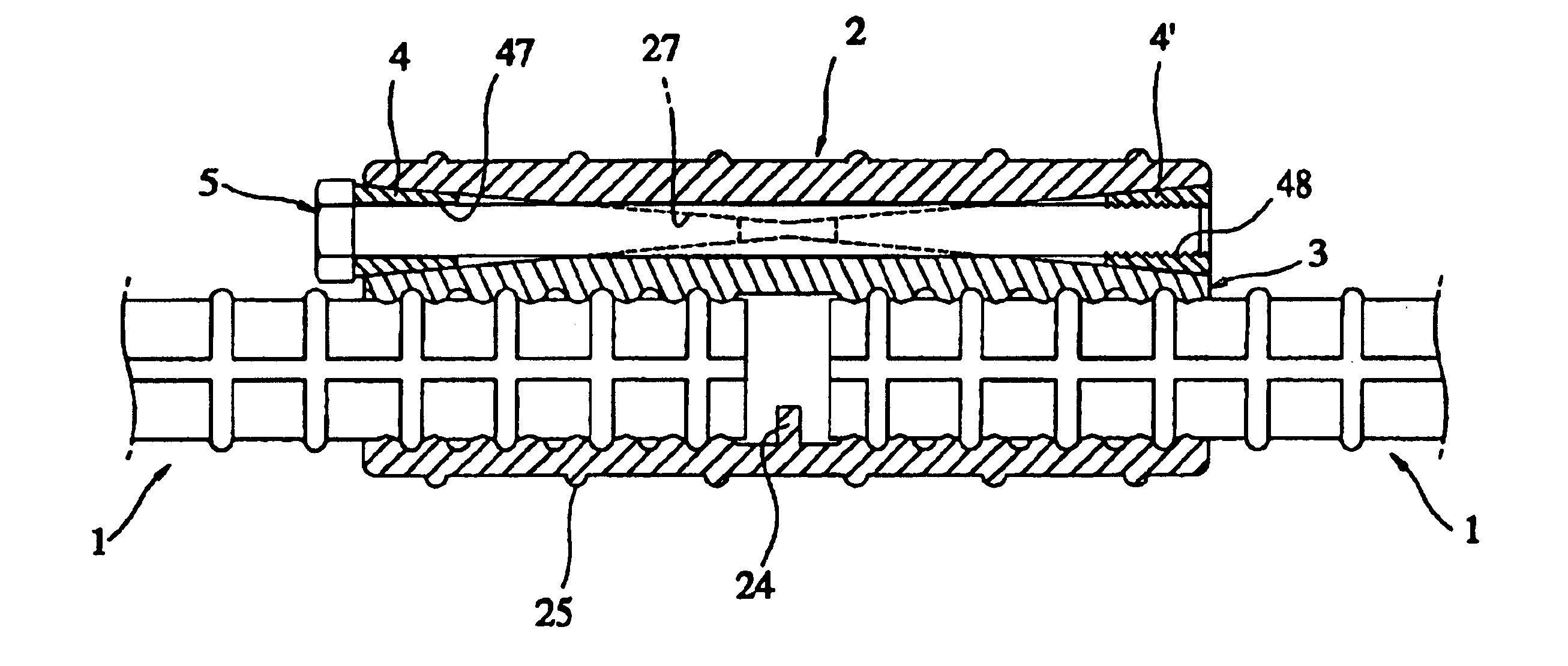
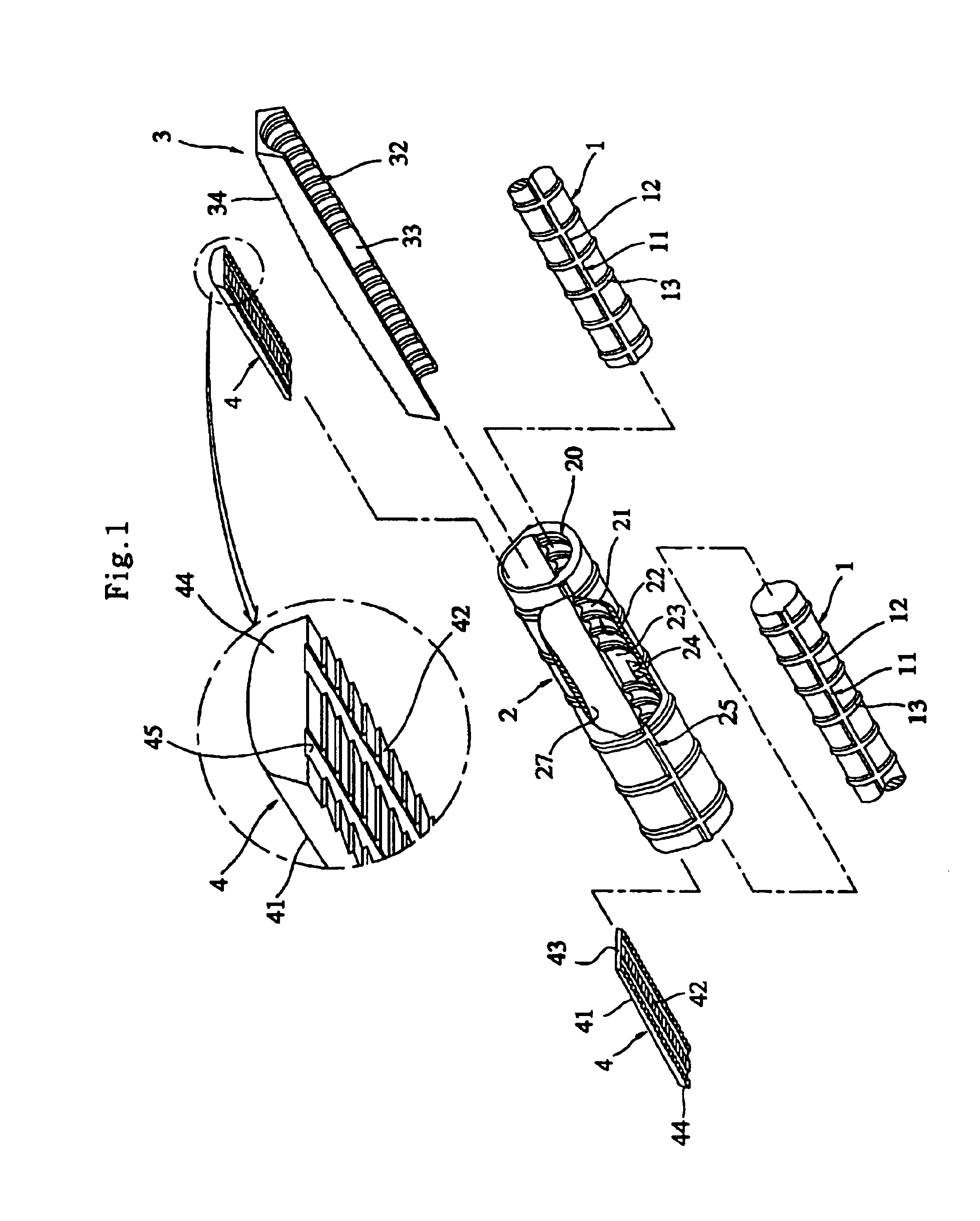
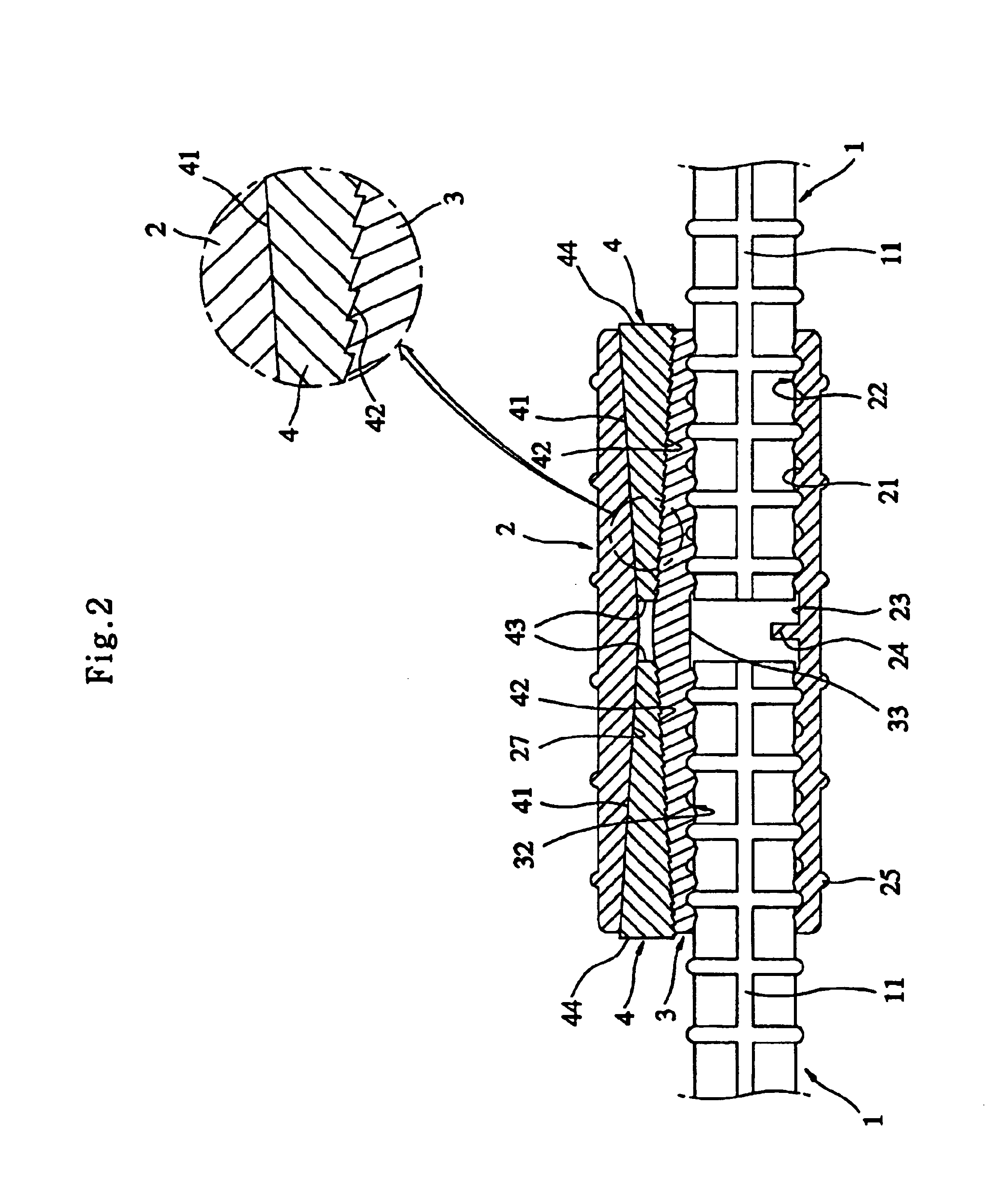
FIGS. 1 to 3 are an exploded perspective view, a cross-sectional view and a transverse cross-sectional view of the present invention, in which the embodiment of the present invention comprises a cylindrical sleeve 2, a intermediate pad 3 and a pair of wedges 4 to join two reinforcing bars 1. A perspective view of a reinforcing bar coupling according to the embodiment of the present invention is shown in FIG. 10, in which the reinforcing bar coupling is assembled.

The reinforcing bars 1, the intermediate pad 3 and wedges 4 are separately inserted or pushed into openings 20 of the cylindrical sleeve 2 of a certain length. The size of the cylindrical sleeve is designed according to the diameter of the reinforcing bars to be joined. To this end, the cross section of the cylindrical sleeve 2 assumes a shape similar to an ellipse.

As is well known in the art, a reinforcing bar is evenly formed at its outer surface with ribs to improve strength and adhesion to the concrete. The cylindrical s...

second embodiment

The method of coupling reinforcing bars according to the present invention can be advantageously applied to an operation of coupling new reinforcing bars to existing reinforcing bars 1 which have been previously arranged, or to existing reinforcing bars 1 which are embedded in poured concrete where adhesive force between the existing reinforcing bars and the concrete may be weakened by impact shocks acting on the wedges.

The stopper 24, the ribs 25 and the inner slant face 27 of this embodiment have the same shapes and functions as those of the first embodiment.

FIGS. 7 to 9 show a third embodiment of the present invention. The essential configuration of this third embodiment is substantially equal to that of the first and second embodiments, except that the driving direction of the wedges 4 is perpendicular or transverse to the reinforcing bars. To this end, a cylindrical sleeve 2 is formed with two wedge fitting openings 29, which are oriented to be perpendicular or transverse to th...

fourth embodiment

Referring to FIGS. 11 to 13, there is shown the present invention. This embodiment is designed to be applied in the case where shapes and positions of semi-annular ribs formed on the outer surfaces of the reinforcing bars provided by various manufacturers are different from one another. That is, where grooves of an uneven surface of an intermediate pad do not coincide with semi-annular ribs of a reinforcing bar in position, the area of the contact surface between the intermediate pad and the reinforcing bar is reduced. To accommodate such nonconformity between the grooves of the intermediate pad and the semi-annular ribs of the reinforcing bars, this embodiment is intended to allow the intermediate pad to be slightly displaced to conform to the reinforcing bar.

To this end, the intermediate pad 3 comprises three intermediate sub pads, as shown in FIG. 11. In other words, the intermediate pad 3 comprises a first intermediate pad 51 and a pair of second intermediate pads 52. The second...


PUM


Abstract

A reinforcing bar coupling is provided for simply and quickly applying to a mechanical butt joint of two bars in the concrete constructions. The reinforcing bar coupling is consisted of a cylindrical sleeve (2) formed an uneven inner surface (22) to mate with the ribs (11) formed around outer surface of the reinforcing bars (1), an intermediate pad (3) having an uneven semi-circular surface at one side and an inclined-declined flat surface at opposite side, a gap provided between the cylindrical sleeve (2) and the intermediate pad (3), and a pair of wedges (4) being inserted into the gap. The inner surface of the cylindrical sleeve (2) and the outer surface of the reinforcing bars (1) are radially compressed to provide the butt joint of the two bars (1) by the wedging action.

Description

BACKGROUND OF THE INVENTION1. Field of the InventionThe present invention relates, in general, to a coupling and, more particularly, to a reinforcing bar coupling which is intended to obtain a mechanical butt-joint between the ends of two reinforcing bars in reinforced concrete work to enhance the strength of the coupled portion and to afford a prompt and convenient coupling operation.2. Related Prior ArtSince reinforcing bars are produced at certain unit lengths from factories, building works for various structures such as bridges, retaining walls and apartment houses, which extend to several tens of meters in length, require the ends of reinforcing bars to be overlapped. As conventional methods for joining reinforcing bars, a few joint processes are commonly used, which are disclosed as follows.In the prior art, a lap-joint process, which is carried out in such a way that the ends of reinforcing bars are lapped along certain lengths thereof and the lapped ends of the reinforcing b...

Claims


Application Information

Patent Timeline
Patent Type & Authority Patents(United States)
IPC IPC(8): E04C5/16E04C5/18
CPCE04C5/165Y10T403/551Y10T403/7067Y10T403/7066Y10T403/7051Y10T403/7052Y10T403/7064Y10T403/57Y10T403/32501Y10T403/5793Y10T403/7069Y10T403/5781Y10T403/50E04C5/16
Inventor KIM, YONG-KEUN
Owner KIM EE
Learn More