Reflection type projection optical system, exposure apparatus and device fabrication method using the same

a projection optical system and exposure apparatus technology, applied in the field of exposure apparatuses, can solve the problems of difficult to meet the requirements of using, the optical system could not include any lenses, and the high na is difficult to maintain, and achieves the effect of simple configuration and good imaging performan

Inactive Publication Date: 2005-03-01
CANON KK
View PDF9 Cites 9 Cited by
  • Summary
  • Abstract
  • Description
  • Claims
  • Application Information

AI Technical Summary

Benefits of technology

Accordingly, it is an exemplified object of the present invention to provide a reflection type projection optical system with a simple configuration and good imaging performance, an exposure apparatus using the same, and a device fabrication method.

Problems solved by technology

The recent trend has required that the resolution be a smaller value; however it is difficult to meet this requirement using only the increased NA, and the improved resolution expects use of a shortened wavelength.
No applicable glass materials have been proposed for the EUV light as exposure light, and a projection optical system could not include any lenses.
Apparently, a two-mirror system is the minimum number, but it is difficult to maintain a high NA and good imaging performance only with two mirrors due to its limited freedom of design.
As a result, it becomes difficult to arrange one aperture stop and instead two non-circular stops become needed, disadvantageously causing the configuration complex.

Method used


Image

  • Reflection type projection optical system, exposure apparatus and device fabrication method using the same
  • Reflection type projection optical system, exposure apparatus and device fabrication method using the same
  • Reflection type projection optical system, exposure apparatus and device fabrication method using the same

Examples


Embodiment Construction

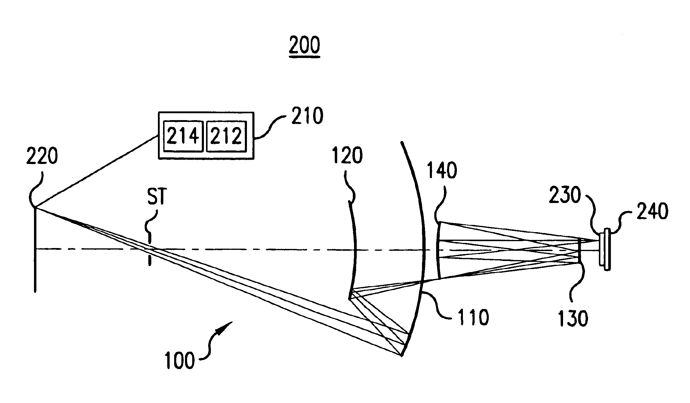
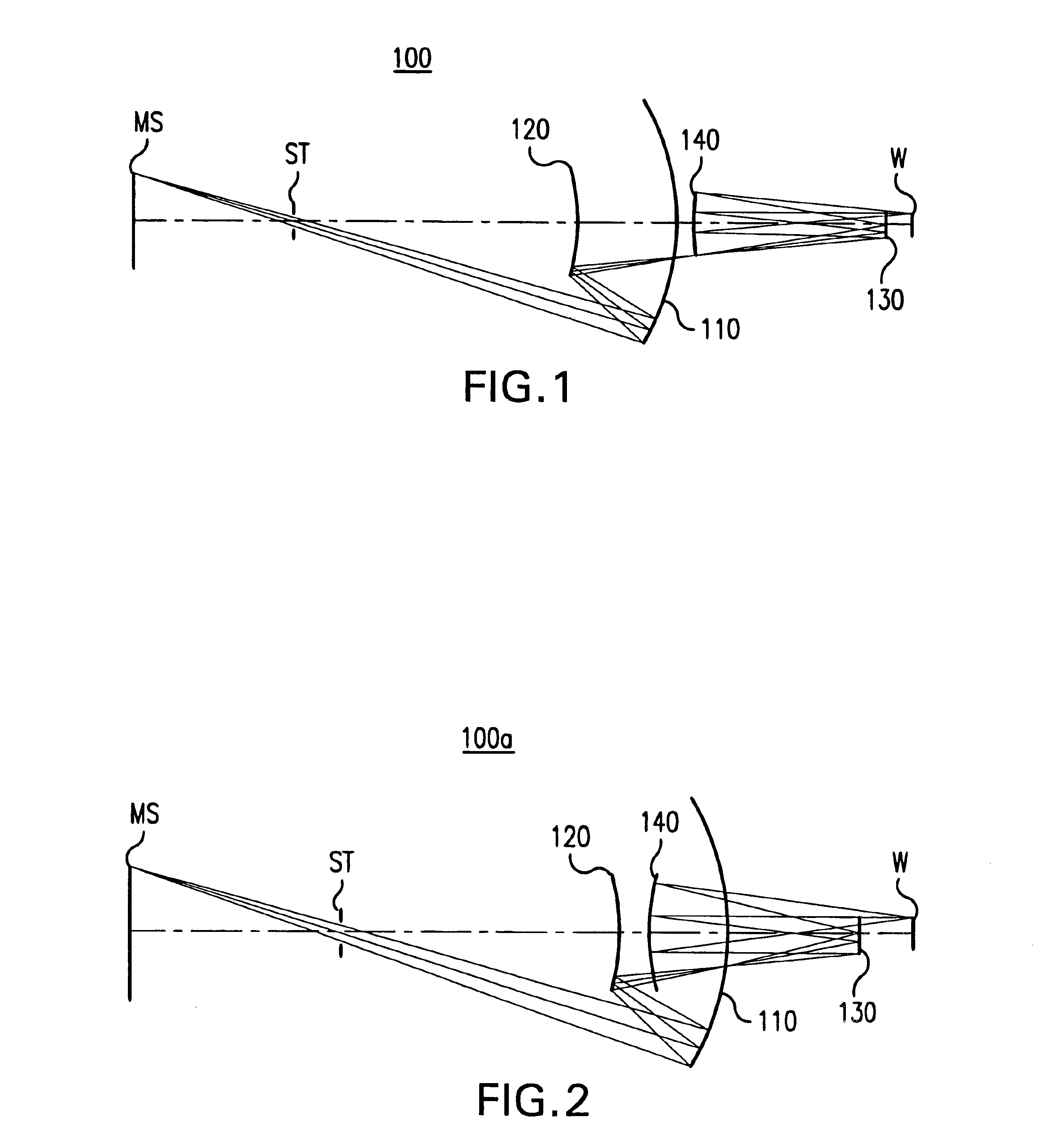
A description will now be given of a reflection type projection optical system 100 and an exposure apparatus 200 as one aspect of the present invention with reference to the accompanying drawings. The present invention is not limited to these embodiments and each element is replaceable within a scope that achieves the objects of the present invention. The same reference numeral in each figure denotes the same element, and a description thereof will be omitted. Here, FIG. 1 is a schematic sectional view showing the reflection type projection optical system 100 and its optical path of one embodiment according to the present invention. FIG. 2 is a schematic sectional view showing a reflection type projection optical system 100a and its path as a variation of the reflection type reduction projection optical system 100 shown in FIG. 1. Unless otherwise specified, the reflection type projection optical system 100 generalizes the reflection type reduction projection optical system 100a. FI...


PUM

PropertyMeasurementUnit
wavelengthaaaaaaaaaa
sizeaaaaaaaaaa

Abstract

A reflection type projection optical system for projecting a pattern on an object surface onto an image surface and forming an imaging system that forms an intermediate image between the object surface and image surface includes four or more mirrors arranged substantially as a coaxial system to reflect light from an object side to an image side, reflection surfaces on the four or more mirrors forming the same direction for forming a reflection angle.

Description

BACKGROUND OF THE INVENTIONThe present invention relates generally to exposure apparatuses, and more particularly to a reflection type (cataoptric) projection optical system, an exposure apparatus, and a device fabricating method using the same. The reflection type projection optical system use ultraviolet (“UV”) and extreme ultraviolet (“EUV”) light to project and expose an object, such as a single crystal substrate for a semiconductor wafer, and a glass plate for a liquid crystal display (“LCD”).Along with recent demands for smaller and lower profile electronic devices, finer semiconductor devices to be mounted onto these electronic devices have been increasingly demanded. For example, the design rule for mask patterns has required that an image with a size of a line and space (“L & S”) of less than 0.1 μm be extensively formed and it is expected to require circuit patterns of less than 80 nm in the near future. The L & S denotes an image projected onto a wafer in exposure with eq...

Claims


Application Information

Patent Timeline
Patent Type & Authority Patents(United States)
IPC IPC(8): G02B17/06G02B17/00G03F7/20G02B27/18H01L21/027
CPCG02B17/0657G03F7/70275G03F7/70233
Inventor TERASAWA, CHIAKI
Owner CANON KK
Why Eureka
Try Eureka