
Fuel cell power systems and methods of operating fuel cell power systems

Inactive Publication Date: 2005-02-22
EMERGENT POWER
View PDF3 Cites 47 Cited by
  • Summary
  • Abstract
  • Description
  • Claims
  • Application Information

AI Technical Summary

Problems solved by technology

Because the current-voltage curve of a fuel cell can vary widely with load, the output voltage of a fuel cell may not be well-matched to the battery voltage in many instances.
A further problem is a need to provide DC to DC conversion to a commercially useful voltage.

Method used


Image

  • Fuel cell power systems and methods of operating fuel cell power systems
  • Fuel cell power systems and methods of operating fuel cell power systems
  • Fuel cell power systems and methods of operating fuel cell power systems

Examples


Embodiment Construction

ing an exemplary methodology for controlling fuel cells of the fuel cell power systems depicted in FIGS. 15 and 17.

[0028]FIG. 18B is a flow chart depicting an exemplary methodology for controlling fuel cells of the fuel cell power systems depicted in FIGS. 15 and 17 to implement exemplary battery maintenance operations.

[0029]FIG. 19 is a graphical representation of electrical status of batteries of a fuel cell power system during different modes of charge.

[0030]FIG. 20 is an illustrative representation of exemplary control signals configured to control power conditioning circuits of a fuel cell power system.

DETAILED DESCRIPTION OF THE PREFERRED EMBODIMENTS

[0031]This disclosure of the invention is submitted in furtherance of the constitutional purposes of the U.S. Patent Laws “to promote the progress of science and useful arts” (Article 1, Section 8).

[0032]According to one aspect of the present invention, a fuel cell power system comprises a fuel cell configured to generate electrica...


PUM


Abstract

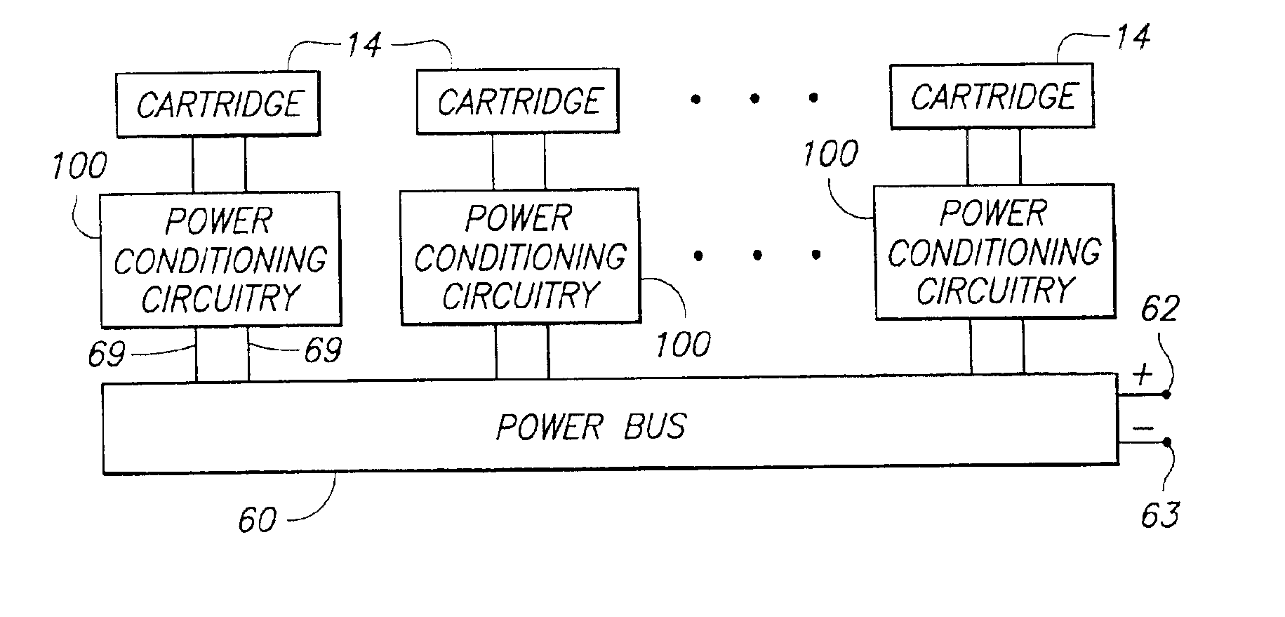
Fuel cell power systems and methods of operating fuel cell power systems are described. According to one aspect, a fuel cell power system includes a fuel cell configured to generate electrical energy; switch mode power conditioning circuitry configured to electrically condition the electrical energy generated by the fuel cell, wherein the switch mode power conditioning circuitry comprises a controller configured to monitor an electrical status of the fuel cell and to adjust the conditioning of the electrical energy using the switch mode power conditioning circuitry responsive to the monitoring, wherein the controller is configured to provide a pulse width modulated control signal to control the switching of the switch mode power conditioning circuitry and to vary a duty cycle of the control signal to adjust the conditioning of the electrical energy using the switch mode power conditioning circuitry.

Description

TECHNICAL FIELD[0002]This invention relates to fuel cell power systems and methods of operating fuel cell power systems.BACKGROUND OF THE INVENTION[0003]Fuel cells are known in the art. The fuel cell is an electrochemical device which reacts hydrogen, and oxygen, which is usually supplied from the ambient air, to produce electricity and water. The basic process is highly efficient and fuel cells fueled directly by hydrogen are substantially pollution free. Further, since fuel cells can be assembled into stacks of various sizes, power systems have been developed to produce a wide range of electrical power output levels and thus can be employed in numerous applications.[0004]Fuel cell power systems which need an energy buffer for occasional load surges can utilize batteries to supply energy needs which exceed the energy production capacity of a fuel cell. The output of one of more fuel cells can be coupled to one or more batteries, which provide energy storage for handling temporary l...

Claims


Application Information

Patent Timeline
IPC IPC(8): H01M8/04
CPCH01M8/0432H01M8/04544H01M8/04552H01M8/04559H01M8/04567H01M8/04574H01M8/04597H01M8/04873H01M8/0488H01M8/04888H01M8/04947H01M8/04955H01M8/249H01M16/006H02J7/34Y02P90/40Y02E60/50Y02E60/10
Inventor SCHMIDT, TIMOTHY J.DEVRIES, PETER D.DODGE, JONATHAN
Owner EMERGENT POWER
Learn More