
Tub mounted, vertically oriented pump

a technology of vertical orientation and washing machine, which is applied in the direction of washing machines with receptacles, other washing machines, textiles and papermaking, etc., can solve the problems of settling of sediment and other materials passing through the water cavity on top adverse effects on the performance of the washing machine, and the location of the pump and the water cavity, so as to reduce the susceptibility to debris, facilitate inspection and cleaning, and facilitate servi

Inactive Publication Date: 2005-02-22
MAYTAG
View PDF38 Cites 14 Cited by
  • Summary
  • Abstract
  • Description
  • Claims
  • Application Information

AI Technical Summary

Benefits of technology

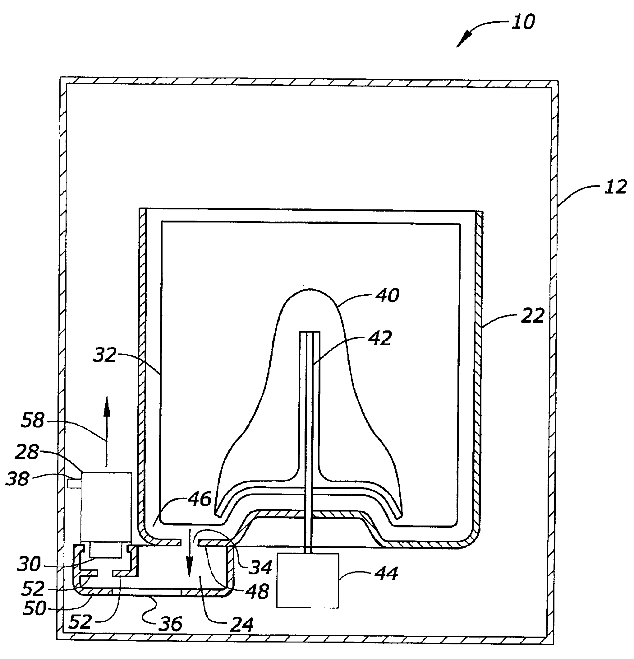
The present invention relates to a washing machine having a tub-mounted, vertically oriented dropped-impeller pump. According to the present invention, the washing machine has an outer tub, a water cavity positioned beneath the outer tub, and a pump mounted on an upper surface of the water cavity and outside of the outer tub, the pump impeller extending downward into the water cavity. The placement of the pump provides the advantage of debris settling away from the pump and its impeller, thereby protecting the pump and the impeller from damage. The pump can be located towards the front of the washing machine making it more accessible for servicing.
The present invention also provides for a washing machine having a service port positioned along a lower surface of the water cavity for providing access to the water cavity. This placement of the service port makes the water cavity easier to inspect and clean. In addition, the water cavity is formed integral with the outer tub to decrease susceptibility to debris and to improve serviceability.
The present invention also provides for a method of servicing a washing machine where the washing machine has a water cavity positioned beneath an outer tub, a pump mounted on an upper surface of the water cavity, and an impeller extending downward into the water cavity. The method includes opening a service port located at the bottom of the water cavity and then accessing the water cavity through the service port. This method of servicing is convenient and less labor intensive than other methods. The present invention also provides for inspecting the water cavity, cleaning the water cavity, and / or accessing the pump.

Problems solved by technology

One problem with this configuration is that sediment and other material passing through the water cavity settle on top of the pump and motor.
This can result in material or debris becoming lodged into the pump resulting in adverse effects on the performance of the washing machine.
Yet another problem in the prior art is that the pump and water cavity are not located near the outer tub.
These connections provide additional opportunities for material or debris to collect, create blockages, or otherwise interfere with the proper operation of the washing machine.
A further problem is that due to the location of the pump and motor, in order to access the water cavity for servicing, the washing machine must be disassembled so that the water cavity can be inspected and cleaned of debris if necessary.

Method used


Image

  • Tub mounted, vertically oriented pump
  • Tub mounted, vertically oriented pump
  • Tub mounted, vertically oriented pump

Examples


Embodiment Construction

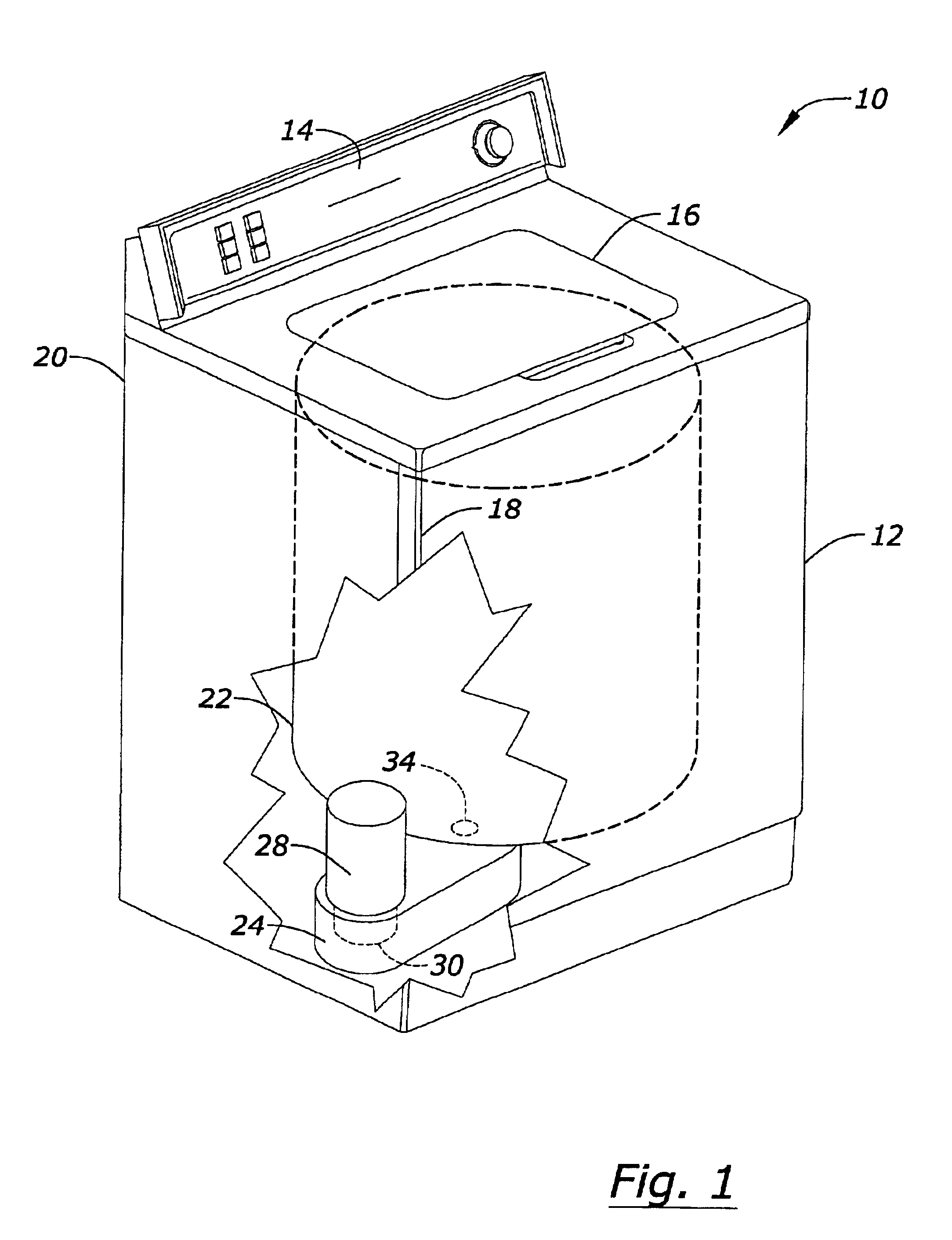
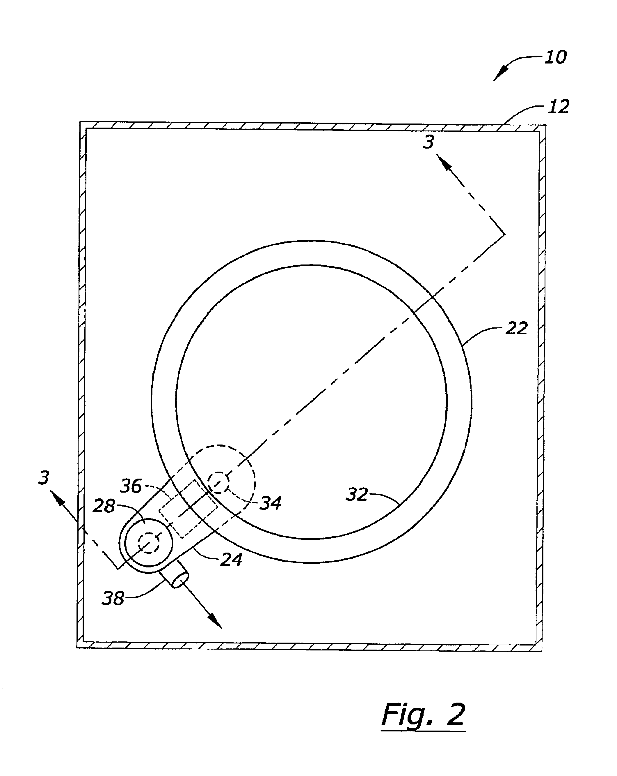
The present invention provides for an improved washing machine having a tub-mounted, vertically oriented drop-impeller pump. FIG. 1 shows a perspective view of the washing machine 10 with a portion cut out. The washing machine 10 includes a cabinet or housing 12 and a control panel 14. The washing machine 10 shown includes a lid 16. Although a top-loading washing machine is shown, the present invention can also be used on a front loading washing machine. The washing machine 10 has a front side 18 and a rear side 20. Within the washing machine 10 is an outer tub 22. Water from the outer tub 22 flows into the water cavity 24 through a water cavity inlet 34.

A pump 28 is mounted outside the water cavity 24 and nearer the front end 18 of the washing machine 10 than the rear end 20 of the washing machine 10. Locating the pump 28 towards the front end 18 of the washing machine 10 provides easier access to service the pump 28. The pump 28 is a dropped impeller pump, having an impeller 30 th...


PUM


Abstract

The present invention includes a washing machine having a water cavity position beneath an outer tub and a pump mounted above the water cavity with an impeller extending downwardly into the water cavity. Preferably, the water cavity is integral with the outer tub and the water cavity includes a service port located along the bottom of the water cavity.

Description

BACKGROUND OF THE INVENTIONThis invention relates to washing machines. More specifically, this invention relates to a washing machine having a tub-mounted and vertically oriented pump.Washing machines typically include a motor-pump assembly. The pump is used to remove water from the machine. Pumps may include impellers used for forcing water in a desired direction such as through an outlet. Many prior art washing machines mount the pump motor below the water cavity, through which water is pumped from the machine. One problem with this configuration is that sediment and other material passing through the water cavity settle on top of the pump and motor. This can result in material or debris becoming lodged into the pump resulting in adverse effects on the performance of the washing machine. Service personnel may be required to remove the sediment or material or fix any resulting damage.Yet another problem in the prior art is that the pump and water cavity are not located near the out...

Claims


Application Information

Patent Timeline
Patent Type & Authority Patents(United States)
IPC IPC(8): D06F39/08D06F37/00D06F37/26
CPCD06F37/26D06F39/085D06F37/267
Inventor HANSEN, TED L.JOHNSON, DARYL T.WHITE, WILLIAM R.VANDE HAAR, EVAN R.DORENKAMP, TIMOTHY D.
Owner MAYTAG
Learn More